Antenna system generating quasi relativistic radiation

a radiation system and quasi-relativistic technology, applied in the field of antenna systems, can solve the problems of dumping relativistic charged particles after applications impose serious x-rays, affecting the operation of relativistic radiation apparatuses, so as to avoid charge neutralization, prevent the generated radiation from being absorbed in air, and high laser intensity

Active Publication Date: 2015-12-01
NATIONAL TSING HUA UNIVERSITY
View PDF14 Cites 2 Cited by
  • Summary
  • Abstract
  • Description
  • Claims
  • Application Information

AI Technical Summary

Benefits of technology

[0021]In accordance with another aspect of the present invention using a laser excitation source having photon energy lower than the working function of the photoemitter, a high laser intensity can be used to induce multi-photon emission from the photoemitter or an anode electrode with a positively biased voltage can be arranged adjacent to the photoemitter in the quasi charged particle generation unit to assist the photoemission through the Schottky effect.

Problems solved by technology

In prior arts, the near-speed-of-light charged particles, usually electrons, are prepared by a large-size and expensive particle accelerator system.
The radiation device, such as the undulator or a bending magnet, is also very bulky, heavy, and expensive.
Furthermore, dumping relativistic charged particles after an application imposes serious x-ray and pray radiation hazard to a user or an operator of relativistic radiation apparatus.
Consequently, most relativistic radiation is only available in a national-scale user facility having careful and extensive radiation shielding.

Method used


Image

  • Antenna system generating quasi relativistic radiation
  • Antenna system generating quasi relativistic radiation
  • Antenna system generating quasi relativistic radiation

Examples


Embodiment Construction

[0032]The present invention will now be described more specifically with reference to the following embodiments. It is to be noted that the following descriptions of preferred embodiments of this invention are presented herein for the purposes of illustration and description only; it is not intended to be exhaustive or to be limited to the precise form disclosed.

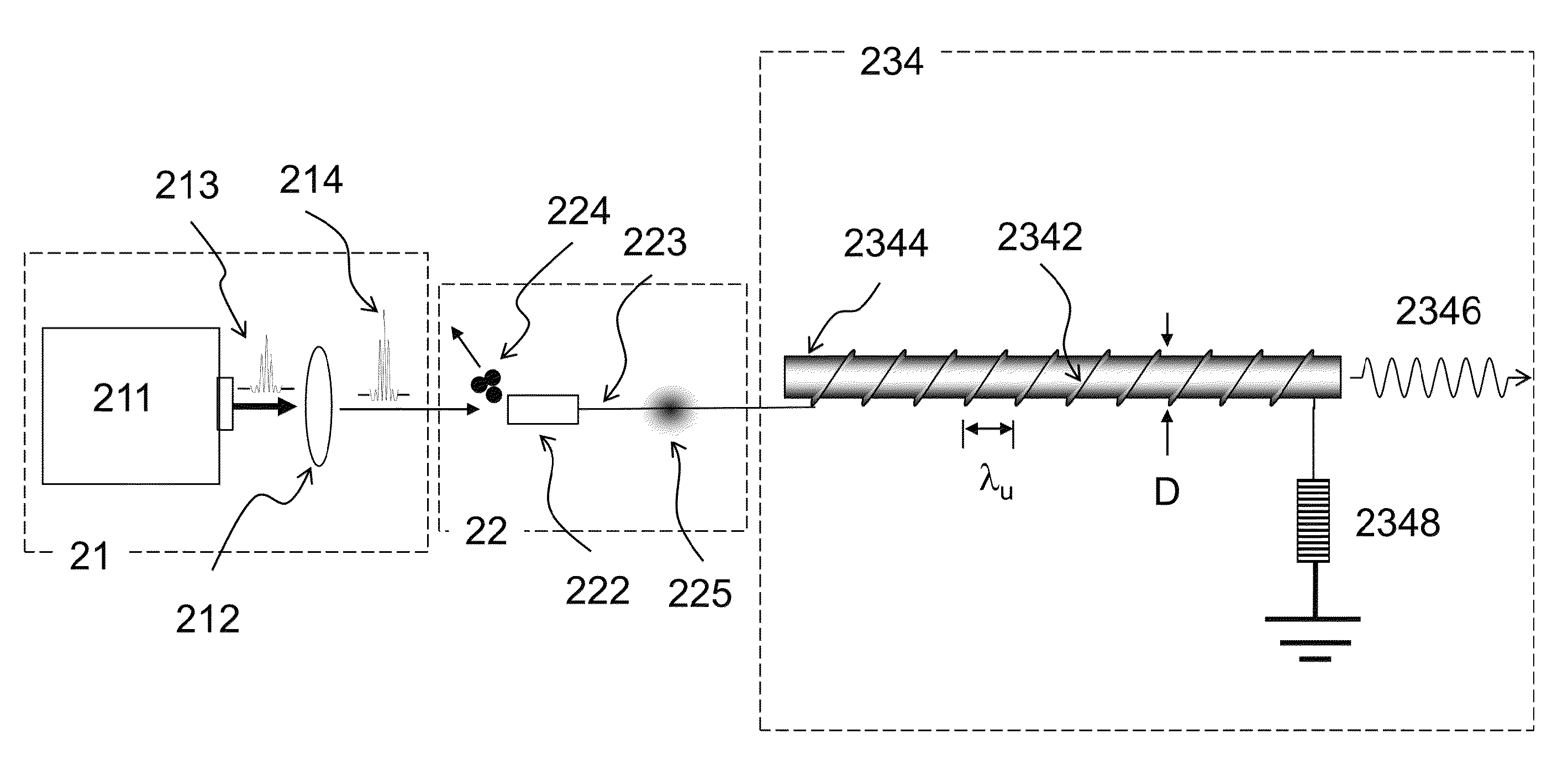
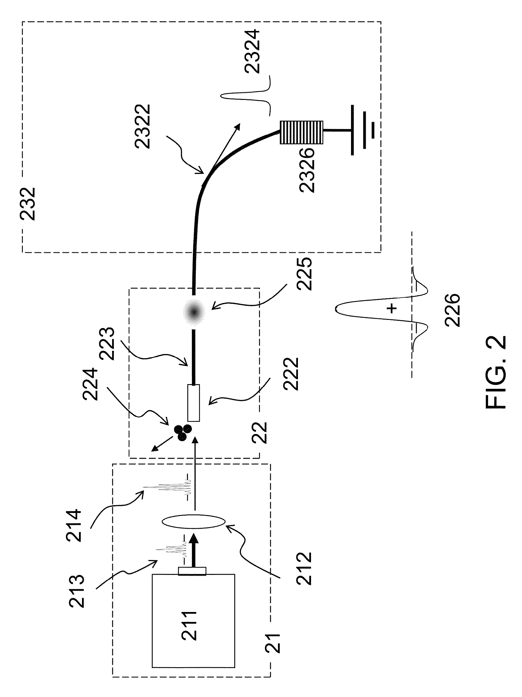
[0033]Refer to FIG. 2, which shows an antenna system radiating a kind of quasi relativistic radiation, called “quasi bending-magnet radiation”, according to a first preferred embodiment of the present invention. The laser excitation unit 21 comprises a laser source 211 and a laser focusing device 212. The laser source 211 emits a short laser pulse 213, which is focused by the laser focusing device 212 and becomes a high intensity laser pulse 214 before entering a quasi charged particle generation unit 22. The quasi charged particle generation unit 22 contains a photoemitter or a photocathode 222 connected to a conducting wir...


PUM


Abstract

An antenna system that generates radiation similar to that generated by a relativistic charged particle is provided. The antenna system includes a conducting wire carrying a current pulse with a net charge, called a quasi charged particle, which propagates near the speed of light and emits radiation. Preferably, the quasi charged particle is generated by using a pulsed laser to knock out electrons from the conducting wire. While propagating on the conducting wire near the speed of light, the quasi charged particle generates a synchrotron like radiation from a bent of the wire, an undulator like radiation from a sinusoidal or helical structure of the wire, a diffraction like radiation from an aperture transmitting the wire, a Smith-Purcell like radiation from a corrugated grating surface next to the wire, and a greatly wavelength-contracted undulator like radiation from an undulator with the wire aligned along the undulator axis.

Description

FIELD OF THE INVENTION[0001]The present invention relates to an antenna system, and, in particular, to a radiation antenna system that generates radiation from an electric pulse carrying a net charge moving on a conducting wire near the speed of light, having a radiation characteristic similar to that generated by a relativistic charged particle moving in vacuum.BACKGROUND OF THE INVENTION[0002]Electromagnetic radiation has been very useful in a wide range of applications, such as communication, imaging, remote sensing, material processing, medical therapy, scientific investigation, etc. It is well known that radiation generation requires acceleration or deceleration (acceleration in the negative sense) of charged particles. For example, an alternating-current (AC) electric power supply may drive electrons in a radiation antenna to generate electromagnetic radiation. In prior arts, the radiation frequency from a stationary antenna is the same as the driving frequency of the power su...

Claims


Application Information

Patent Timeline
Patent Type & Authority Patents(United States)
IPC IPC(8): H01Q13/08H01L33/06H01Q1/00
CPCH01L33/06H01Q1/00H05G2/00
Inventor HUANG, YEN-CHIEHWU, MING-HSIUNGHUANG, KUAN-YANCHEN, CHIA-HSIANGWANG, YI-CHU
Owner NATIONAL TSING HUA UNIVERSITY
Why Eureka
Try Eureka