Conversion of hydrocarbons to carbon dioxide and electrical power
a technology of hydrocarbons and conversion processes, applied in the direction of hydrogen separation using liquid contact, machines/engines, energy input, etc., can solve the problems of endothermic steam reforming reactions, large amount of heat energy generated by atr, and large amount of energy consumed by atr, so as to improve the flexibility of atr process and simplify heat exchange demands
Active Publication Date: 2015-12-22
JOHNSON MATTHEY PLC
View PDF10 Cites 4 Cited by
- Summary
- Abstract
- Description
- Claims
- Application Information
AI Technical Summary
Benefits of technology
This patent describes a process for generating energy from steam reforming while reducing energy demands and improving flexibility. The process involves using a combination of steam reforming and partial cooling to increase the hydrogen content of the gas. The resulting gas mixture is then further converted to produce a hydrogen-rich gas. The integrated gas-heated / secondary reforming process offers improved efficiency and cost savings as compared to existing methods. It also allows for flexible utilization of various feedstocks and can help limit carbon dioxide emissions.
Problems solved by technology
This process has the drawback that the steam reforming reactions are endothermic and consume considerable amounts of energy that would better be converted to power.
These ATR-based processes have the drawback that the ATR generates considerable amounts of heat energy, generally in excess of the process requirements, which is then wasted.
The use of air as the primary oxidant in autothermal reforming and the complexity of the additional heat exchange requirements increases the equipments size and cost.
Moreover, in the ATR flowsheet it would not appear possible to readily adapt the process for less than 100% CO2 capture.
Method used
View moreImage
Smart ImageViewing Examples


Examples
example
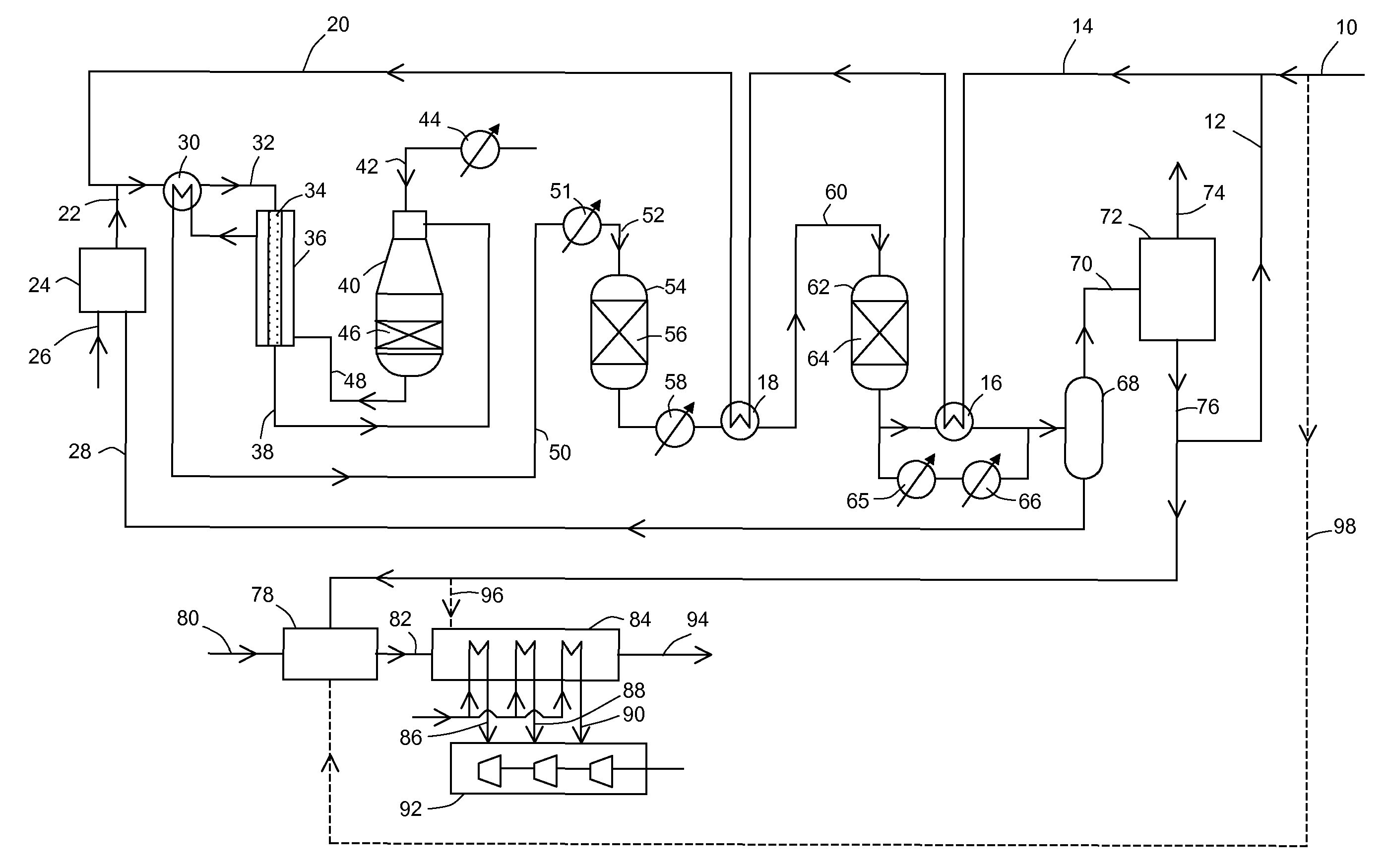
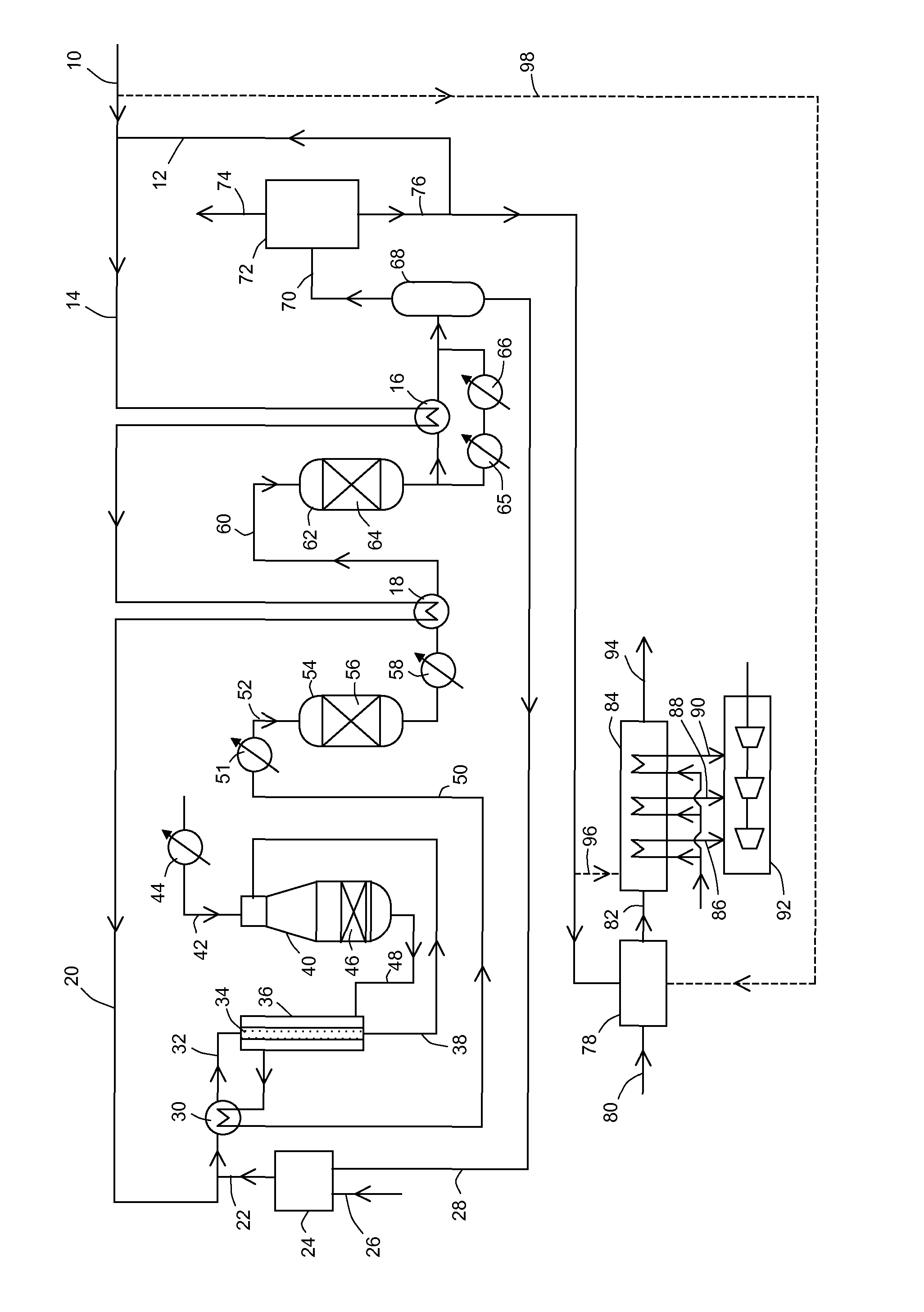
[0064]The invention is further illustrated by the following calculated example of a process in accordance with the flowsheet depicted in FIG. 1. In the following tables, the pressures (P, in bar abs.), temperatures (T, in ° C.) and flow rates (kmol / h) are quoted, rounded to the nearest integer.
Login to View More PUM
| Property | Measurement | Unit |
|---|---|---|
| pressure | aaaaa | aaaaa |
| temperature | aaaaa | aaaaa |
| temperature | aaaaa | aaaaa |
Abstract
A process for the conversion of a hydrocarbon to CO2 and electrical power is described which includes subjecting a gas mixture of a hydrocarbon feed stream and steam to an integrated reforming process including stages of steam reforming in a gas-heated reformer and secondary reforming to generate a reformed gas mixture, increasing the hydrogen content of the reformed gas mixture by subjecting it to one or more water-gas-shift stages, cooling the resulting hydrogen-enriched reformed gas and separating condensed water therefrom, passing the resulting de-watered hydrogen-enriched reformed gas to one or more stages of carbon dioxide separation to recover carbon dioxide, combusting the remaining hydrogen-containing fuel stream with an oxygen containing gas in a gas turbine to generate electrical power and passing the exhaust gas mixture from the gas turbine to a heat recovery steam generation system that feeds one or more steam turbines to generate additional electrical power.
Description
CROSS-REFERENCE TO RELATED APPLICATIONS[0001]This application is the U.S. National Phase application of PCT International Application No. PCT / GB2010 / 051991, filed Nov. 30, 2010, and claims priority of British Patent Application No. 0922411.4, filed Dec. 22, 2009, the disclosures of both of which are incorporated herein by reference in their entireties for all purposes.FIELD OF THE INVENTION[0002]This invention relates to processes for the conversion of hydrocarbons, such as natural gas, to carbon dioxide and electrical power.BACKGROUND OF THE INVENTION[0003]Processes for converting natural gas to CO2 and electricity via so-called natural gas combined cycle (NGCC) processes are becoming increasingly important as power producers seek routes to reduce carbon dioxide emissions.[0004]US 2008 / 0155984 discloses a process for producing power and partially capturing CO2 comprising stream reforming in a pre-steam-methane reformer a mixture of hydrocarbon and steam at <800° C. to form a fir...
Claims
Login to View More Application Information
Patent Timeline
 Patent Type & Authority Patents(United States)
IPC IPC(8): C01B3/38F02C3/28F01K23/06C01B3/48C01B3/50C01B3/52C01B31/20F01K17/06F01K23/10C01B32/50
CPCC01B3/382C01B3/48C01B3/501C01B3/52C01B31/20F01K17/06F01K23/067F01K23/10F02C3/28C01B2203/0233C01B2203/0244C01B2203/0283C01B2203/0288C01B2203/043C01B2203/0405C01B2203/0415C01B2203/0495C01B2203/06C01B2203/0811C01B2203/0838C01B2203/0866C01B2203/0883C01B2203/0888C01B2203/0894C01B2203/1011C01B2203/1047C01B2203/1058C01B2203/1076C01B2203/1082C01B2203/127C01B2203/1235C01B2203/1241C01B2203/1294C01B2203/143C01B2203/148C01B2203/84F05D2220/72F05D2220/722F05D2220/75Y02P20/129C01B32/50Y02E20/18Y02E50/10Y02P20/10
Inventor MCKENNA, MARKABBOTT, PETER EDWARD JAMESFARNELL, PETER WILLIAM
Owner JOHNSON MATTHEY PLC
Features
- R&D
- Intellectual Property
- Life Sciences
- Materials
- Tech Scout
- Unparalleled Data Quality
- Higher Quality Content
- 60% Fewer Hallucinations
Learn More Browse by: Latest US Patents, China's latest patents, Technical Efficacy Thesaurus, Application Domain, Technology Topic, Popular Technical Reports.
© 2025 PatSnap. All rights reserved.Legal|Privacy policy|Modern Slavery Act Transparency Statement|Sitemap|About US| Contact US: help@patsnap.com