
Membrane filtration process with high water recovery

a membrane filtration and high water recovery technology, applied in the direction of membranes, separation processes, multi-stage water/sewage treatment, etc., can solve the problems of large amount of membrane concentrate (or “reject”) to be further treated or disposed of at a high cost, and the efficiency and water recovery is often limited

Active Publication Date: 2016-02-23
BL TECH INC
View PDF14 Cites 16 Cited by
  • Summary
  • Abstract
  • Description
  • Claims
  • Application Information

AI Technical Summary

Benefits of technology

The patent describes a method for improving the efficiency and water recovery rate of reverse osmosis and nanofiltration processes for water purification. The method involves first pretreating the influent solution using various techniques to remove suspended solids and adjust the pH. Then, CO2 is injected into the pretreated solution to increase bicarbonate concentration. The conditioned solution is then flowed through a membrane filtration unit, which includes reverse osmosis or nanofiltration membranes. The membrane filtration unit produces a permeate solution and a retentate solution. The retentate solution is then treated in a precipitation clarifier to cause precipitation of solids, resulting in a supernatant solution and a reject solution. The supernatant solution is then recirculated and combined with the influent solution prior to the pretreatment step. The method helps to remove hardness and silica-related fouling components, as well as some organic compounds, and increase water recovery rates for reverse osmosis and nanofiltration processes.

Problems solved by technology

In reverse osmosis and nanofiltration processes, efficiency and water recovery is often limited by mineral scale formation from hardness compounds, such as calcium, magnesium, barium, iron, fluoride, sulfate, carbonate and silica or silicate salts on membrane surfaces.
Residual organic compounds and biological proliferation can also cause membrane fouling.
As such, a large amount of the membrane concentrate (or “reject”) has to be further treated or disposed of at a high cost.

Method used


Image

  • Membrane filtration process with high water recovery
  • Membrane filtration process with high water recovery
  • Membrane filtration process with high water recovery

Examples


Embodiment Construction

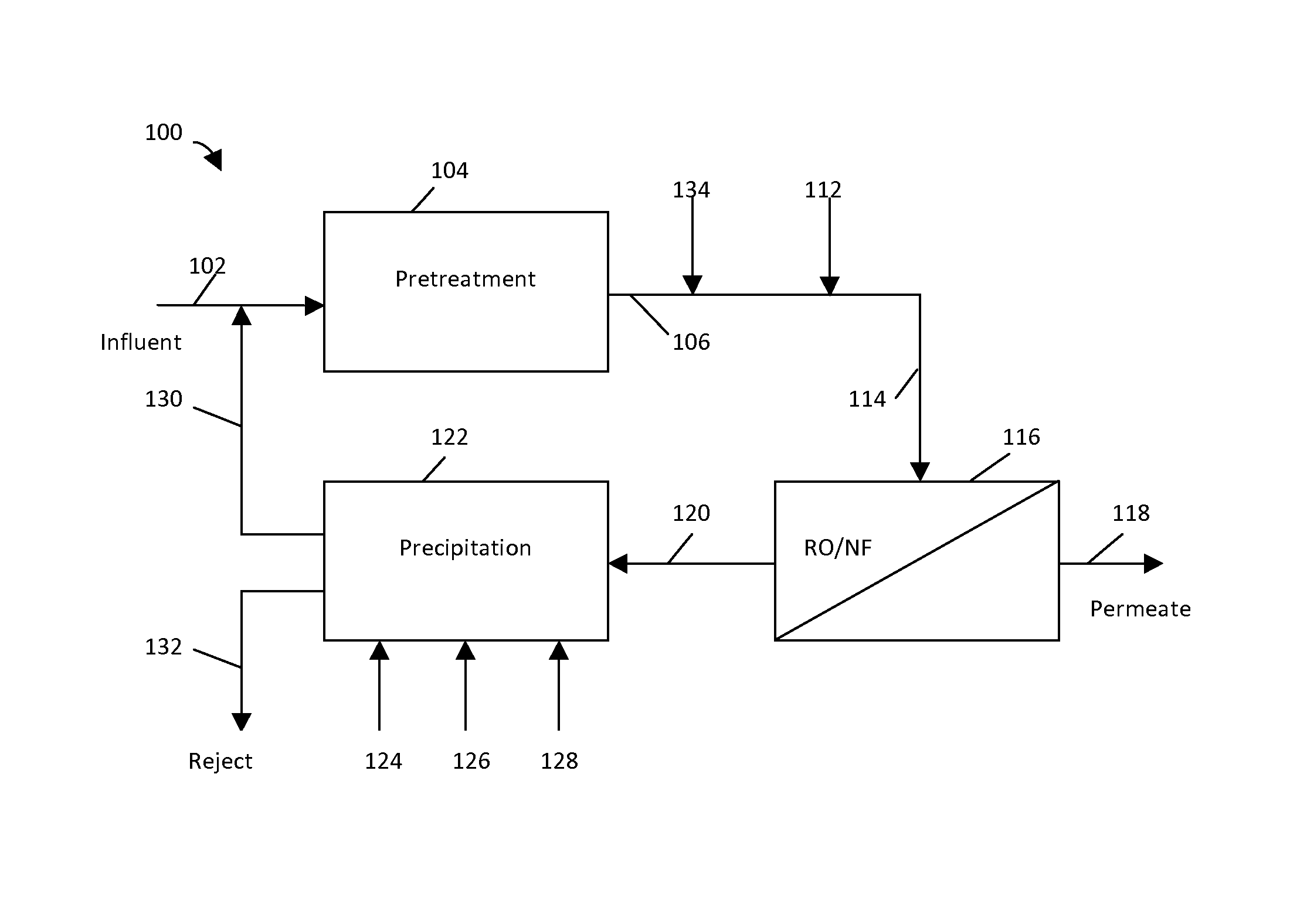
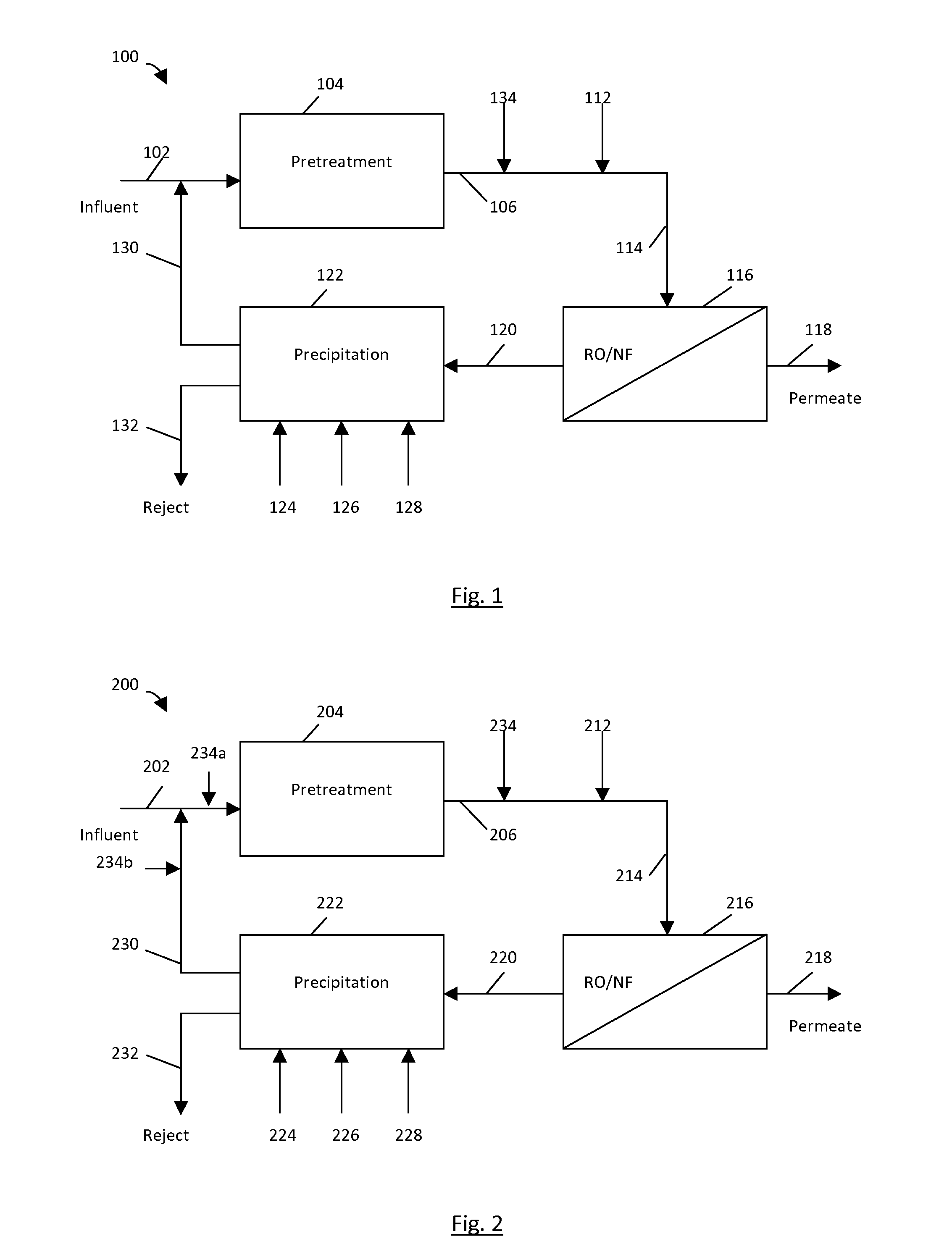
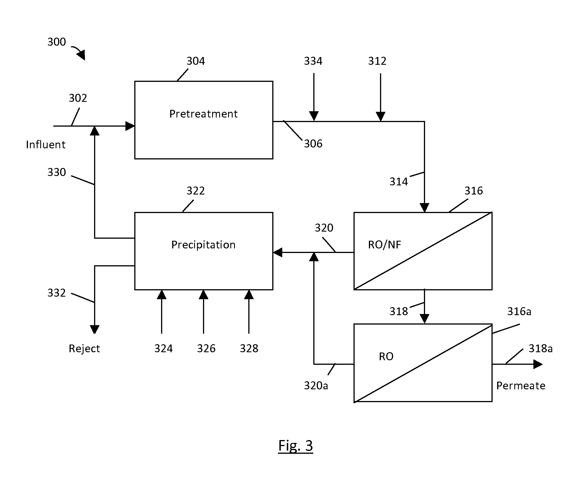
[0012]Referring to FIG. 1, an example of a filtration apparatus is shown generally at 100. The filtration apparatus 100 includes an influent solution 102. The influent solution 102 is introduced to a pretreatment chamber 104. The pretreatment chamber 104 includes suitable means effective to remove suspended solids from the influent solution 102, using ultrafiltration, microfiltration or multimedia filtration, for example.

[0013]After pretreatment, pH of the pretreated solution 106 is adjusted to at least about 8.3 or lower by injecting CO2 134. Optionally, an anti-scalant agent 112 can be added to prevent membrane scaling. Examples of anti-scalant agents include polyacrylic acids, hydrolyzed polymaleic anhydride, acrylic or maleic acid based copolymer and terpolymer, and metal sequestering agents such as ethylenediaminetetraacetic acid (EDTA), sodium hexametaphosphate (SHMP), 1-hydroxyethylidene-1,1-diphosphonic (HEDP), and 2-phosphonobutane-1,2,4-tricarboxylic acid (PBTC).

[0014]Afte...


PUM

PropertyMeasurementUnit
pHaaaaaaaaaa
pHaaaaaaaaaa
concentrationaaaaaaaaaa

Abstract

A membrane filtration process includes pretreating an influent solution to remove suspended solids, to produce a pretreated solution. pH of the pretreated solution is adjusted to at least 8.3 or lower by injecting CO2 into the pretreated solution, to produce a conditioned solution. Injecting CO2 also serves to supplement bicarbonate in the conditioned solution. The conditioned solution is flowed through a membrane filtration unit, to produce a permeate solution and a retentate solution. The membrane filtration unit comprises reverse osmosis membranes or nanofiltration membranes, or both. The retentate solution is then treated to cause precipitation, to produce a supernatant solution and a reject solution. At least a portion of the supernatant solution is recirculated by combining it with the influent solution prior to the step of pretreating.

Description

FIELD[0001]This specification relates to reverse osmosis and nanofiltration processes for water purification.BACKGROUND[0002]The following background discussion is not an admission that anything discussed below is citable as prior art or common general knowledge.[0003]High efficiency reverse osmosis processes (“HERO”; see, for example, U.S. Pat. Nos. 5,925,255 and 6,537,456) can achieve higher water recovery rates compared to conventional reverse osmosis processes. HERO relies on a series of pretreatment steps prior to reverse osmosis filtration, which includes use of weak acid cation resin columns, degasification and pH adjustment.[0004]Other processes may involve the use of microfiltration, ultrafiltration, ion exchange and chemical precipitation to achieve greater water recovery (see, for example, U.S. Pat. Nos. 5,501,798, 6,113,797 and 6,461,514).INTRODUCTION[0005]The following discussion is intended to introduce the reader to the more detailed discussion to follow, and not to l...

Claims


Application Information

Patent Timeline
Patent Type & Authority Patents(United States)
IPC IPC(8): B01D61/04C02F1/44B01D61/02C02F9/00B01D61/12C02F1/66C02F5/08B01D61/10C02F1/54C02F1/56C02F1/52
CPCC02F9/00B01D61/022B01D61/025B01D61/027B01D61/04C02F1/441C02F1/442C02F5/08B01D2311/04B01D2311/08B01D2311/18B01D2311/2642B01D2311/2661B01D2317/04C02F1/444C02F1/5236C02F1/54C02F1/56C02F1/66B01D61/029
Inventor WANG, SIJINGZHU, YANRONGHE, GAORONG
Owner BL TECH INC
Learn More