
Method and apparatus for shaping focused laser beams

a laser beam and focused technology, applied in the field of optics, can solve the problems of difficult production and expensive array of optical elements, inability to reliably create small focused beams of a size comparable with the wavelength of the beam, and inability to achieve the effect of suppressing laser energy loss

Active Publication Date: 2016-03-15
ADLOPTICA OPTICAL SYST
View PDF14 Cites 38 Cited by
  • Summary
  • Abstract
  • Description
  • Claims
  • Application Information

AI Technical Summary

Benefits of technology

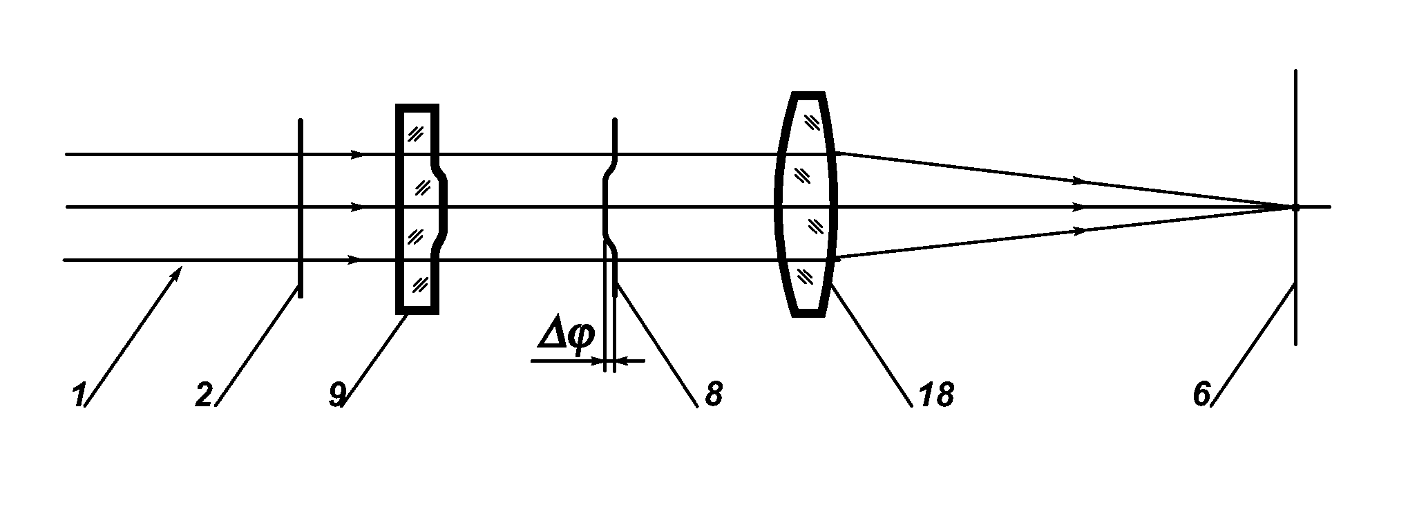
The present invention provides methods, systems, devices, and apparatus for beam shaping laser beams with reduced energy losses and uniform intensity distribution in a focal plane of a focusing lens. The invention also includes a phase transforming optical system in the form of a collimator and at least one lens made from refractive optical material with an optical surface introducing a desired phase shift to a region of a beam based on the shape featuring by a protrusion of a central part of the surface. The shape featuring by a protrusion of a central part of the surface and the smooth transition between the central and peripheral parts of the surface introduce the function of phase shift introduction and the function of beam focusing in one device to create a compact beam shaping solution.

Problems solved by technology

However, from another side, for many scientific and industrial applications the Gaussian profile is not an optimum one because of non-uniform intensity distribution within a laser beam.
An obvious disadvantage of this integration approach is use of complicated, difficult to produce and expensive array optical elements.
Another disadvantage of integration type systems is the strong speckle effect happening due to destroying the beam structure by splitting a beam, thus reducing its spatial coherence, and uncontrolled interference of light from multiple temporally coherent beamlets, this effect makes impossible to reliably create small focused beams of a size comparable with a wavelength of a beam, for example, of about 10 microns diameter in case of Nd:YAG or fiber lasers.
In case of applying the DOE the range of applications can be limited because of unacceptable diffraction losses and low resistance to high power laser beams.
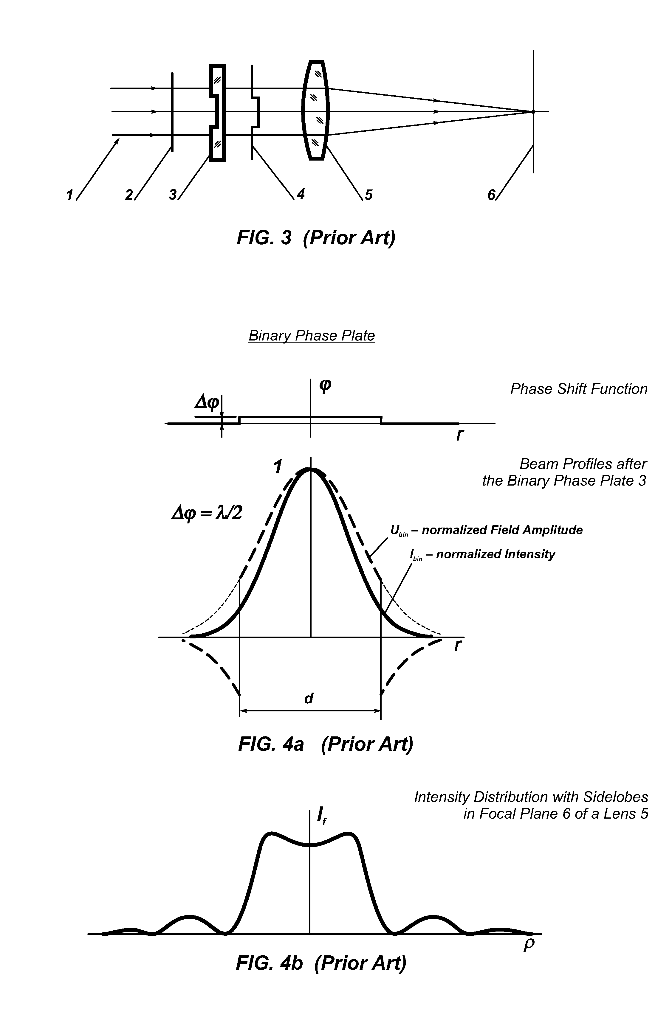
Those sidelobes “contain” relatively high amount of energy and, in most laser technologies, are either useless or bring an unwanted effect on a workpiece.
This is, evidently, loss of costly laser energy that can reach essential values especially in case of high power lasers.
Another disadvantage of this technical solution is in sharp edges of material of the binary phase plate 3 on the border of the regions where this wavefront shift occurs.
In the case of powerful lasers, those edges become zones of overheating and lead to destruction of the binary phase plate, this is especially critical in case of high peak power short pulse lasers.
Thus, from the point of view of modern requirements of beam shaping optics for real laser applications, the conventional solutions are not optimal.

Method used


Image

  • Method and apparatus for shaping focused laser beams
  • Method and apparatus for shaping focused laser beams
  • Method and apparatus for shaping focused laser beams

Examples


Embodiment Construction

[0052]Before explaining the disclosed embodiments of the present invention in detail it is to be understood that the invention is not limited in its applications to the details of the particular arrangements shown since the invention is capable of other embodiments. Also, the terminology used herein is for the purpose of description and not of limitation.

[0053]In the Summary above and in the Detailed Description of Preferred Embodiments and in the accompanying drawings, reference is made to particular features (including method steps) of the invention. It is to be understood that the disclosure of the invention in this specification includes all possible combinations of such particular features. For example, where a particular feature is disclosed in the context of a particular aspect or embodiment of the invention, that feature can also be used, to the extent possible, in combination with and / or in the context of other particular aspects and embodiments of the invention, and in the...


PUM


Abstract

Beam shaping methods, systems, devices and apparatus to provide transformation of a TEM00 beam which intensity distribution is described by the Gaussian or similar functions to a focused spot of round or square shape with uniform intensity distribution achieved through introducing in the TEM00 beam a phase shift function with smooth phase transition and further focusing of the transformed beam; the resulting intensity distributions are created around the focal plane of a focusing optical system. The phase shift function is introduced by a phase transforming optical system implemented in apparatuses of the invention in form of a plate, or a telescope, or a collimator, or integrated to the focusing optical system: the phase transforming optical system including an aspheric optical surface providing the phase shift function with smooth phase transition. As a focusing optical system any diffraction limited optics with positive dioptric power can be applied.

Description

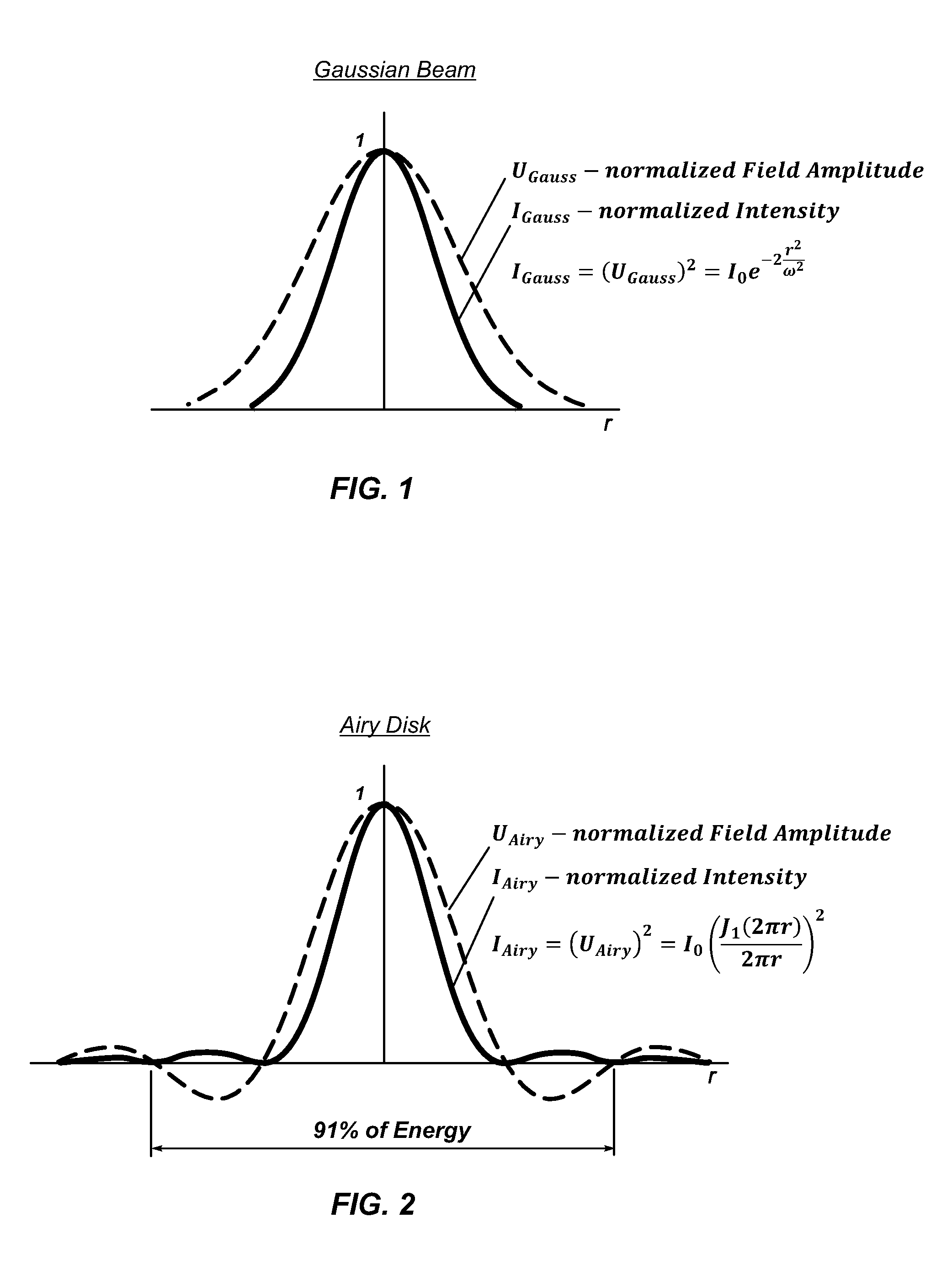
FIELD OF INVENTION[0001]The present invention relates to the field of optics, in particular to optical systems, apparatus, devices and methods for beam shaping being intended to transform intensity distribution of focused laser beams in the focal plane and nearest area.BACKGROUND TO THE INVENTION[0002]Lasers are widely applied in various applications in industry and their effective using is very important. Due to their physics features of creating the laser radiation the intensity profile of laser sources is described, typically, by the Gaussian function, FIG. 1. When focusing a Gaussian laser beam by a lens the intensity distribution in the focal plane of this lens is described by Gaussian function as well—this is well known feature of TEM00 laser beams. This intensity distribution is, also, characteristic one for the planes near the focal plane of a lens, thus, in the most interesting for real application working area around a focal point of a focusing lens the intensity distribut...

Claims


Application Information

Patent Timeline
IPC IPC(8): G02B27/09
CPCG02B27/0927G02B27/095G02B2207/117
Inventor LASKIN, ALEXANDERLASKIN, VADIM
Owner ADLOPTICA OPTICAL SYST
Learn More