
Crack-resistant environmental barrier coatings

a technology of environmental barrier and crack-resistant coating, which is applied in the direction of mechanical equipment, machines/engines, transportation and packaging, etc., can solve the problems of high temperature durability of engine components, prone to defects in conventional ebc application processes discussed above, and high temperature steam stability of silicon oxide, etc., to reduce the incidence and/or extent of cracking, improve the reliability of ebc system, and reduce the stress of tensile hoop

Inactive Publication Date: 2016-03-22
GENERAL ELECTRIC CO
View PDF15 Cites 5 Cited by
  • Summary
  • Abstract
  • Description
  • Claims
  • Application Information

AI Technical Summary

Benefits of technology

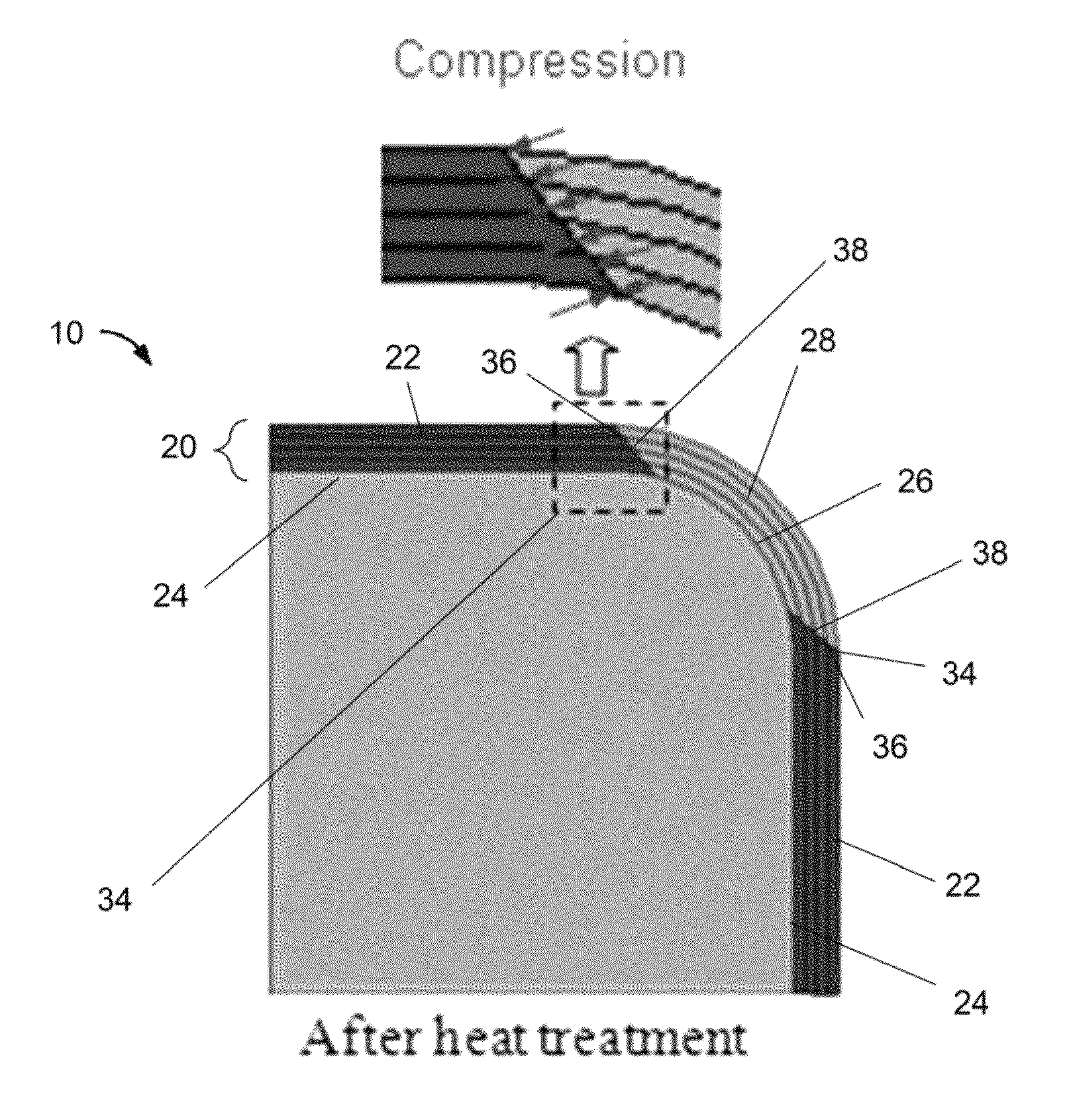
The invention improves the reliability of an EBC system by reducing cracking and delamination without changing its structure or chemical composition. By configuring the system with adjacent portions that have adjacent edges, compressive interfacial stresses can be induced at the edges, which reduces tensile hoop stresses that promote cracking and delamination at corners of the system.

Problems solved by technology

However, as operating temperatures increase, the high temperature durability of the components of the engine must correspondingly increase.
Additionally, silicon oxide is not stable in high temperature steam, but is converted to volatile (gaseous) silicon hydroxide species.
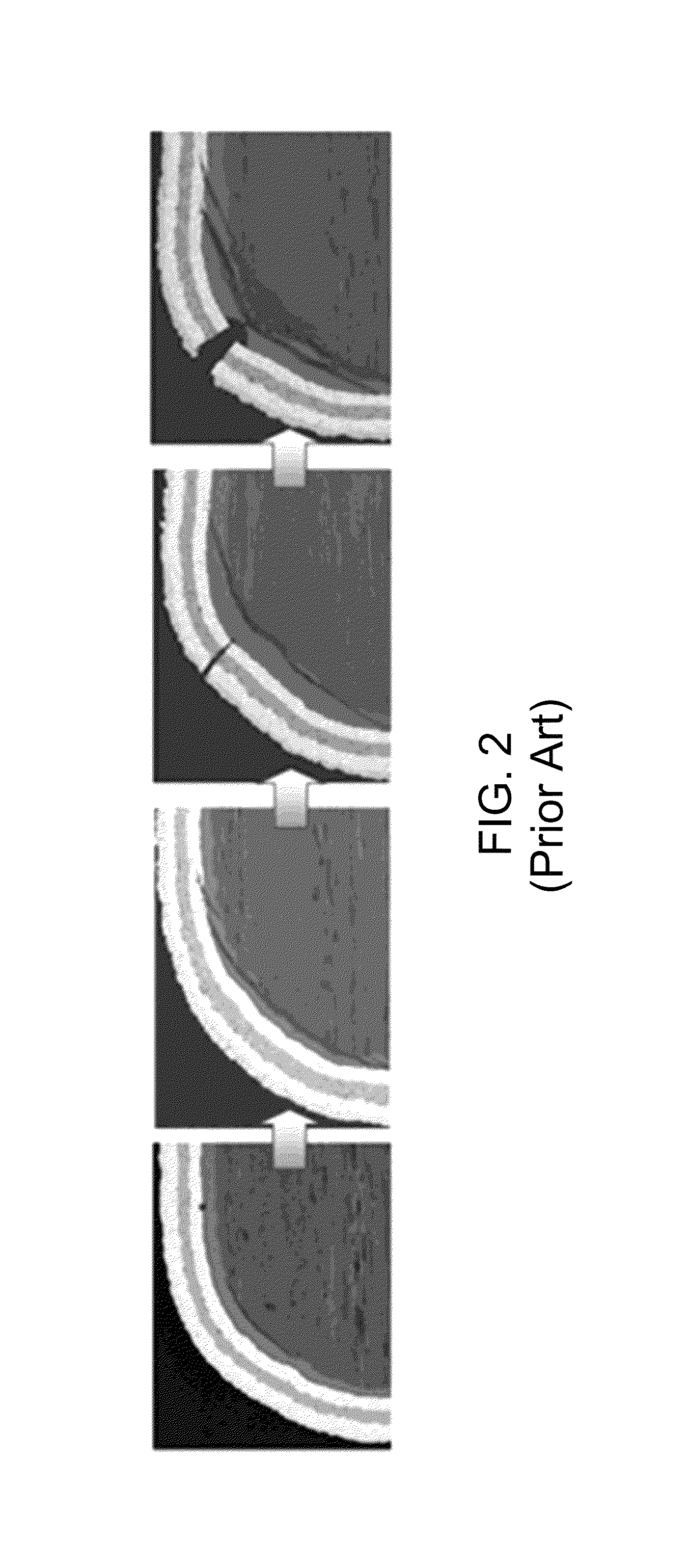
The conventional EBC application processes discussed above are prone to induce defects such as through-the-thickness and interfacial cracks, especially at corners due to tensile strain induced by the heat treatment performed after the application process.

Method used


Image

  • Crack-resistant environmental barrier coatings
  • Crack-resistant environmental barrier coatings
  • Crack-resistant environmental barrier coatings

Examples


Embodiment Construction

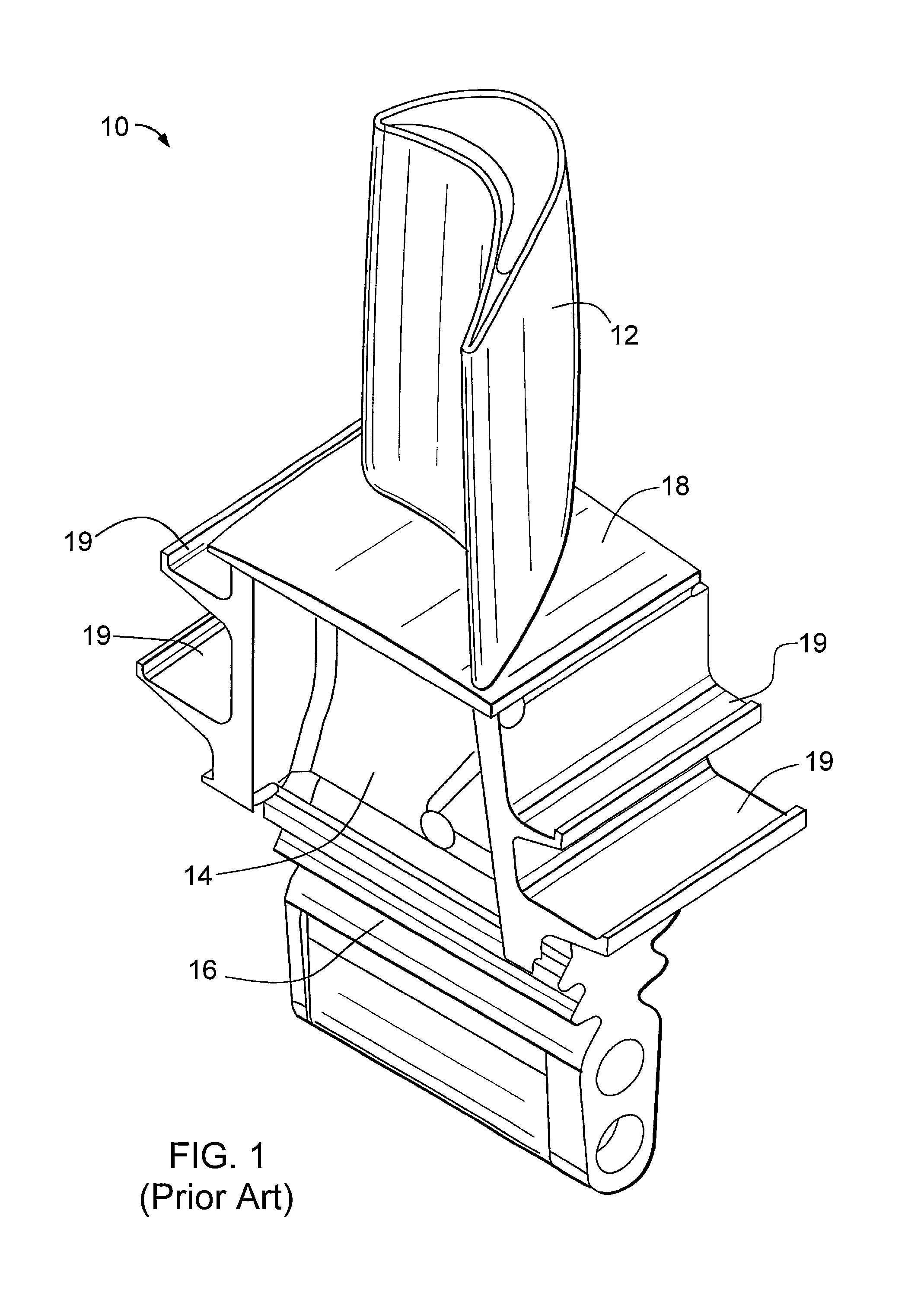
[0020]The present invention is generally applicable to components that operate within environments characterized by relatively high temperatures, severe thermal cycling and stresses, oxidation, and corrosion. Notable examples of such components include high and low pressure turbine vanes (nozzles) and blades (buckets), shrouds, combustor liners, augmentor hardware, and other hot section components of turbine engines, though the invention has application to other components. For clarity, the present invention will be described in reference to a bucket 10 of a land-based gas turbine engine of a type used in the power generation industry as represented in FIG. 1.

[0021]In accordance with embodiments of this invention, the bucket 10 is a silicon-based component. Notable examples of silicon-containing materials include those with a dispersion of silicon carbide, silicon nitride, a silicide (for example, a refractory metal or transition metal silicide) and / or silicon as a reinforcement mat...


PUM

PropertyMeasurementUnit
angleaaaaaaaaaa
angleaaaaaaaaaa
angleaaaaaaaaaa

Abstract

Methods suitable for reducing corner cracking of environmental barrier coating systems. The methods include forming at least one layer of a first portion of the environmental barrier coating system on at least a first region of the component, performing a first heat treatment, forming at least one layer of a second portion of the environmental barrier coating system on a second region of the component, and performing a second heat treatment to the component. Edges of the first portion and edges of the second portion form an angle of at most 60° with respect to a surface of the first region of the component. During the second heat treatment, the second portion of the EBC system expands and the expansion of the second portion of the EBC system is at least partially constrained by the first portion of the EBC system to reduce tensile interfacial stresses in the EBC system.

Description

BACKGROUND OF THE INVENTION[0001]The present invention generally relates to ceramic matrix composite (CMC) components and processes for their production. More particularly, this invention provides a method to reduce corner cracking and delamination of environmental barrier coating (EBC) systems at corners of CMC components.[0002]Higher operating temperatures for gas turbine engines are continuously being sought in order to improve their efficiency. However, as operating temperatures increase, the high temperature durability of the components of the engine must correspondingly increase. Significant advances in high temperature capabilities have been achieved through the formulation of iron, nickel, and cobalt-based superalloys. While superalloys have found wide use for components used throughout gas turbine engines, and especially in the higher temperature sections, alternative lighter-weight component materials have been proposed.[0003]Ceramic matrix composites (CMCs) are a class of...

Claims


Application Information

Patent Timeline
Patent Type & Authority Patents(United States)
IPC IPC(8): B05D5/00C23C4/18C23C16/02C23C16/56C23C4/02C23C30/00C04B41/89F01D5/28C04B41/52C04B41/00
CPCC04B41/009C04B41/52C04B41/89C23C4/18C23C16/02C23C16/56C23C30/00F01D5/288C23C4/02C04B35/565C04B35/806C04B41/5096C04B41/5059C04B41/522C04B41/5066C04B41/5024C04B41/5042F05D2240/121F05D2240/122F05D2240/125F05D2240/303F05D2240/304F05D2240/307Y10T428/24793
Inventor ZHANG, JAMESROBERTS, HERBERT CHIDSEYDAS, RUPAK
Owner GENERAL ELECTRIC CO
Learn More