Composite carbon fibers
a technology of composite carbon fibers and carbon fibers, which is applied in the direction of carbon-silicon compound conductors, cell components, transportation and packaging, etc., can solve the problems of difficult to make a state where each fibrous carbon is dispersed, and difficulty in sufficiently constructing a conductive network, so as to improve battery characteristics such as a capacity retention ratio, easy dispersion, and low electric resistance
- Summary
- Abstract
- Description
- Claims
- Application Information
AI Technical Summary
Benefits of technology
Problems solved by technology
Method used
Image
Examples
production example 1
Preparation of Catalyst
[0098]Aluminum hydroxide (HIGILITE (registered trademark) M-43 manufactured by Showa Denko K.K.) was subjected to heat treatment in the atmosphere where air flows at 850° C. for 2 hours to prepare a carrier.
[0099]In a 300 ml tall beaker, 50 g of pure water was charged, and then 4.0 g of the carrier was added and dispersed to prepare carrier slurry.
[0100]In a 50 ml beaker, 16.6 g of pure water was charged, and then 0.32 g of hexammonium heptamolybdate tetrahydrate (manufactured by Junsei Chemical Co., Ltd.) was added and dispersed. Thereafter, 7.23 g of iron(III) nitrate nonahydrate (manufactured by Kanto Chemical Co., Inc.) was added and dispersed to prepare a catalyst solution.
[0101]In another 50 ml beaker, 32.7 g of pure water was charged, and then 8.2 g of ammonium carbonate (manufactured by Kanto Chemical Co., Inc.) was added and dispersed to prepare a pH control liquid.
[0102]A stirring bar was placed in a tall beaker containing carrier slurry, and then th...
production example 2
Synthesis of Multiwalled Carbon Nanotube: MWCNT
[0103]The catalyst (1.0 g) obtained in Production Example 1 was placed on a quartz boat. The quartz boat was placed at the center in a horizontal tubular furnace (quartz tube: inner diameter of 50 mm, length of 1,500 mm, soaking area of 600 mm). While allowing nitrogen gas to flow through the horizontal tubular furnace at 500 ml / minute, a temperature was raised to 680° C. over 30 minutes. Thereafter, supply of the nitrogen gas was stopped and mixed gasses of ethylene with hydrogen (ethylene concentration of 50% by volume) were allowed to flow at 2,000 ml / minute, followed by reaction for 20 minutes to synthesize multiwalled carbon nanotubes. Supply of the mixed gasses were stopped and the nitrogen gas was supplied. After cooling to room temperature, the multiwalled carbon nanotubes were taken out from the furnace.
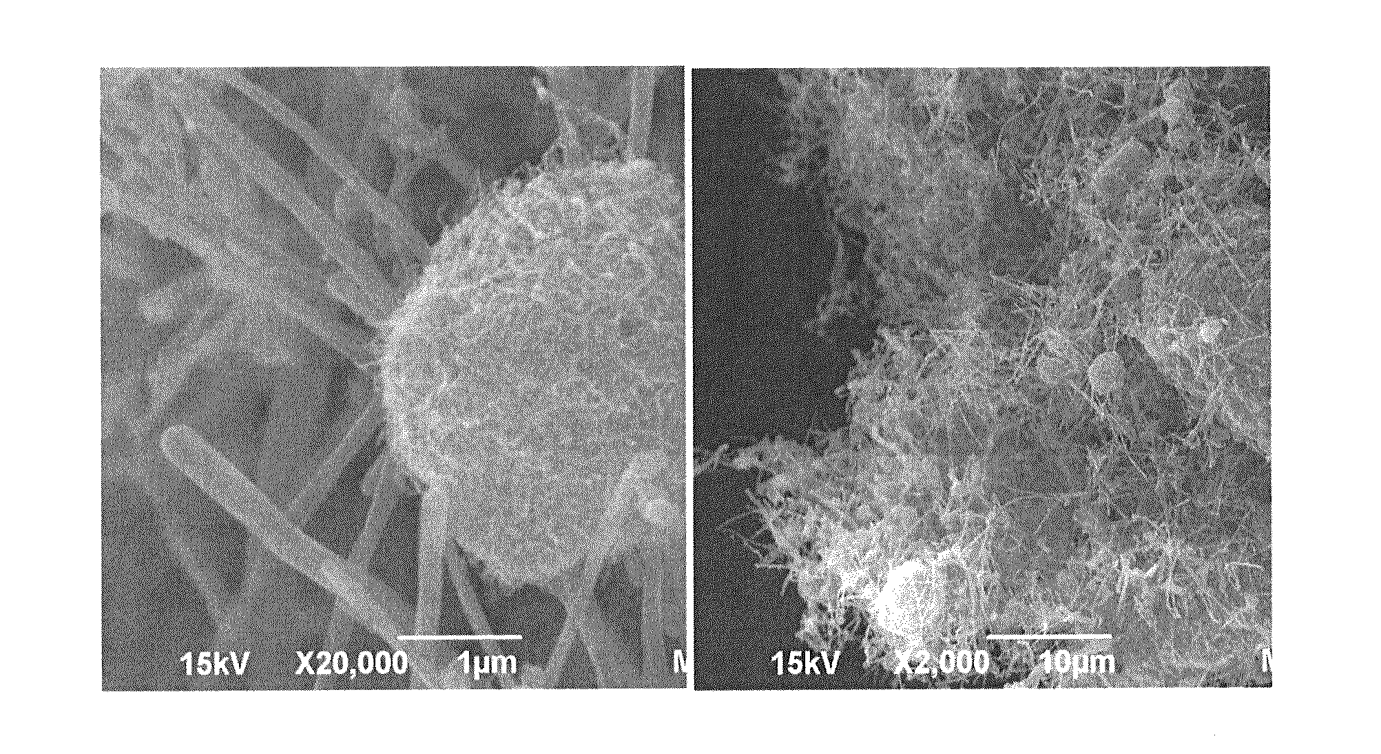
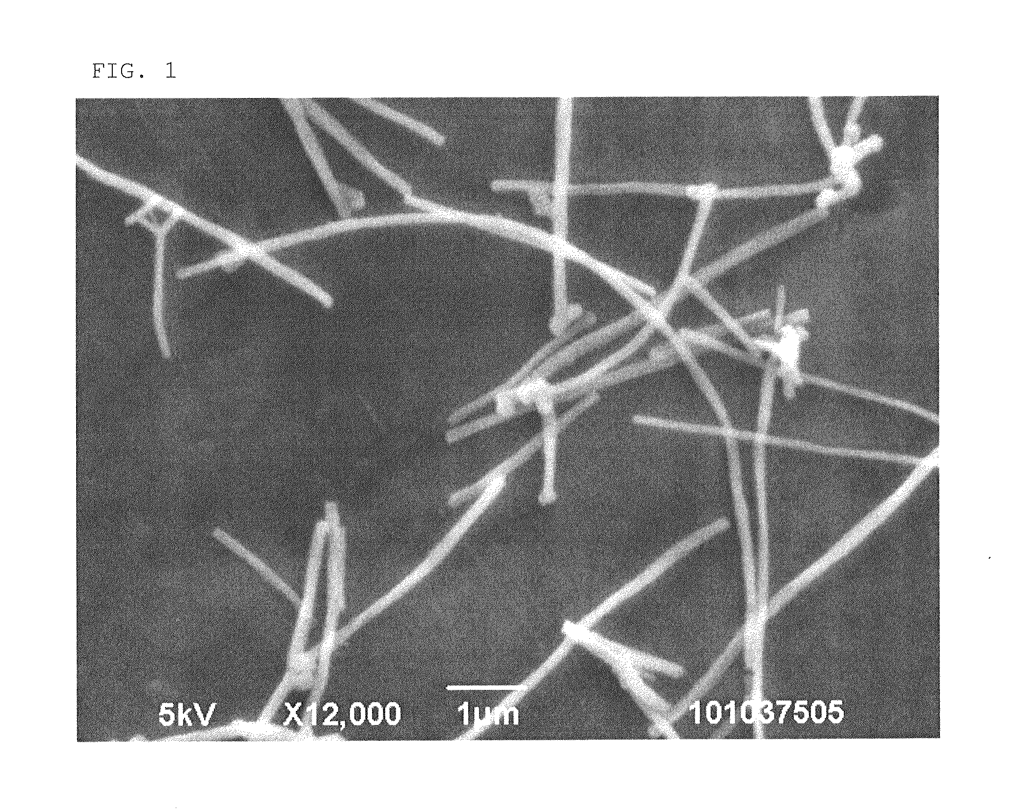
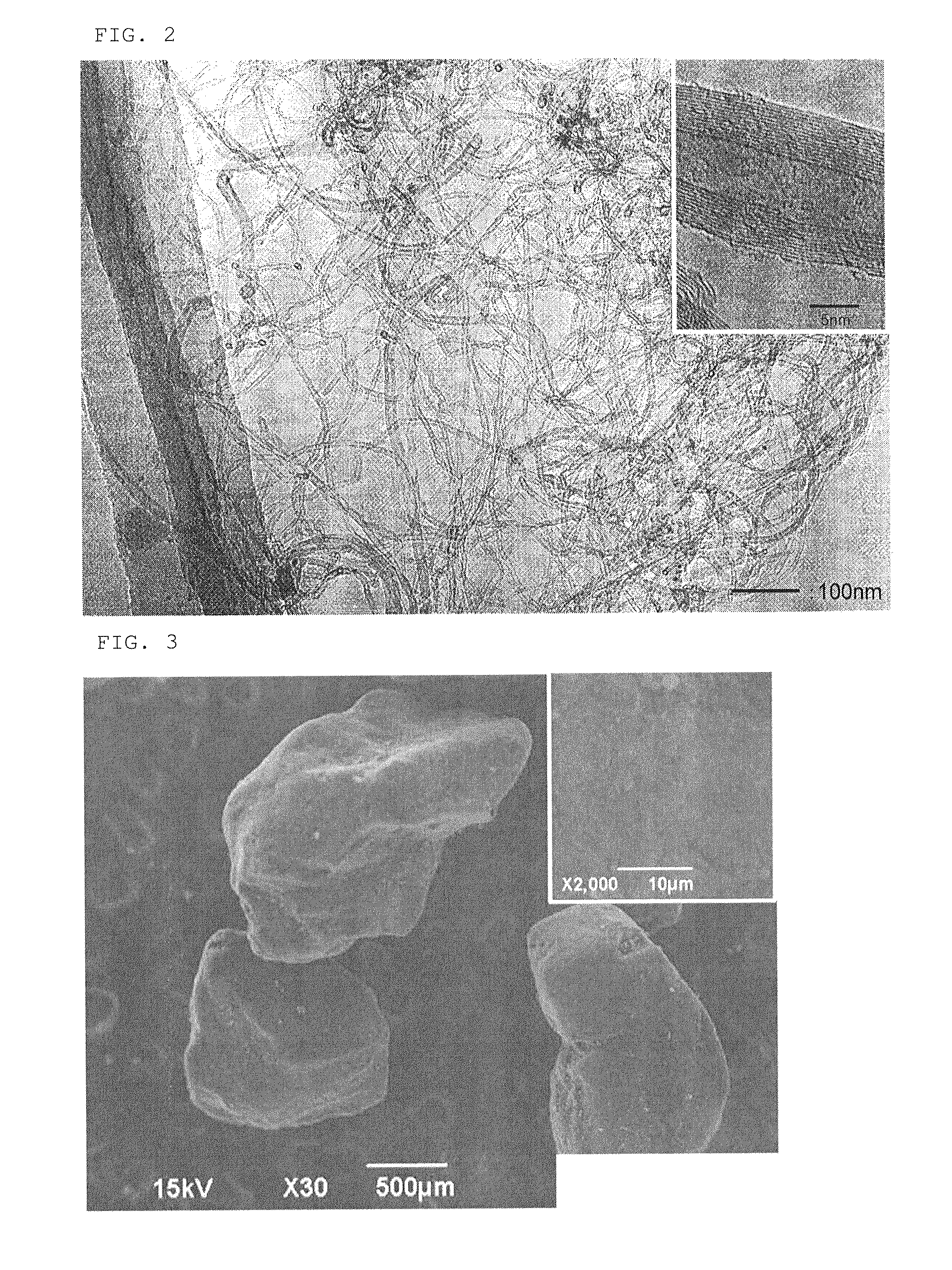
[0104]Fiber shape and powder properties are shown in Table 1. A transmission electron micrograph is shown in FIG. 2, a scannin...
production example 3
Pulverizng of Multiwalled Carbon Nanotube: Pulverized MWCNT Product
[0105]Using a jet mill STJ-200 manufactured by Seishin Enterprise Co., Ltd., the multiwalled carbon nanotubes synthesized in Production Example 2 were supplied at 6 kg / h and pulverized under the conditions of a pusher nozzle pressure of 0.64 MPa and a gliding nozzle pressure of 0.60 MPa. A 50% particle diameter D50 in volume-based cumulative particle size distribution of aggregates was 10 μm.
[0106]Fiber shape and powder properties are shown in Table 1, results of thermal analysis are shown in FIG. 6, and a relation between the load and the compressed density is shown in FIGS. 10 and 11.
PUM
| Property | Measurement | Unit |
|---|---|---|
| diameter | aaaaa | aaaaa |
| diameter | aaaaa | aaaaa |
| compressed density | aaaaa | aaaaa |
Abstract
Description
Claims
Application Information
 - R&D
- Intellectual Property
- Life Sciences
- Materials
- Tech Scout
- Unparalleled Data Quality
- Higher Quality Content
- 60% Fewer Hallucinations
Browse by: Latest US Patents, China's latest patents, Technical Efficacy Thesaurus, Application Domain, Technology Topic, Popular Technical Reports.
© 2025 PatSnap. All rights reserved.Legal|Privacy policy|Modern Slavery Act Transparency Statement|Sitemap|About US| Contact US: help@patsnap.com


