The detection and location of different linear distortions (e.g., from impedance mismatches) in a modern HFC network that carries digital signals is a challenging problem.
However, in a
coaxial cable plant of an HFC network, the use of active TDR becomes tricky because of the presence of a
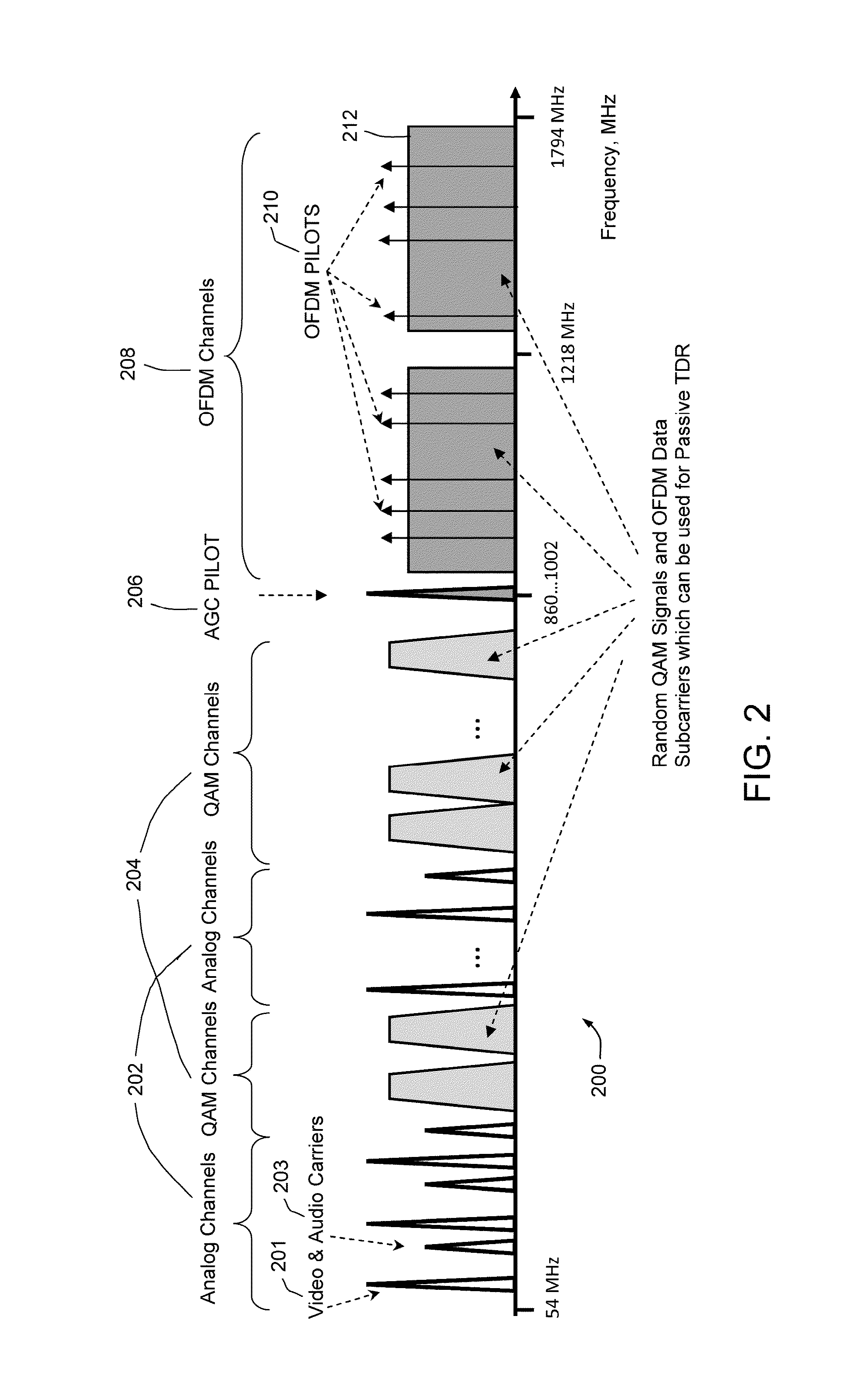
wideband downstream spectrum of service signals, including analog TV channels, digital
QAM channels, digital OFDM signals, AGC pilots, and the like.
The
probe signal or pulse will likely interfere with the service signals.
Thus, active TDR may not be suitable or practical for a commercial HFC network.
The
system proposed in U.S. Pat. No. 7,069,163 to Gunther is not a truly passive technique, however, because it creates a separate
probe signal from the
original data signals and injects the probe signal into the wire under test (which is also carrying the unaltered
original data signals).
Obviously, it is not as accurate as active TDR, and the accuracy is limited by the bandwidth of one upstream
QAM channel.
Obviously, this would provide the most valid confirmation that a problem (mismatch) has been fixed, but it takes extra time, effort and equipment and does not offer the capability of pinpointing the mismatch to less than + / −50 feet.
Also, it is limited to the use of upstream signals only.
However, this method has some drawbacks.
However, this will take time and
impact CM signal traffic.
Another limitation of this method is that
continuous wave (CW) or
narrowband downstream signals, such as analog video carriers, AGC pilots, and OFDM continuous
pilot subcarriers, may be included in the autocorrelation, which would contribute flat or spread components in the autocorrelation function and may cause an echo spike to be masked.
Obviously, for the
scenario of pinpointing linear impairments within the last tens of feet, the
technician will not actually have an opportunity to check linear
distortion by
polling data from nearby CMs.
Also, implementing a method that captures the whole downstream signal in a handheld meter for analysis will not be cost effective, because
high resolution analog-to-
digital converter chips, with sampling rates higher than 2 GHz are needed to capture the downstream signal.
The chips are still very expensive and have high
power consumption (e.g., a few Watts).
Also, to undertake the necessary
signal processing of a full downstream spectrum, a powerful, high cost, high power consuming, computer processor would be required.
Therefore, both methods require a complex analysis of data from many CMs and correlation of data with electronic maps.
However, they are less useful for pinpointing mismatches within the last tens of feet in a field search for mismatches.
(1) The HFC
cable television downstream signal has a very wide bandwidth (e.g., 1 GHz with a probable increase to 1.7 GHz under
DOCSIS 3.1). Therefore, sampling and digitally
processing this signal requires expensive and high power-consuming chipsets, which make it impractical to implement a passive TRD
system in a low-cost handheld unit.
(2) The HFC
cable television downstream signal is not completely random and includes many CW pilots which have flat or spread autocorrelation responses. Such flat responses may
mask an echo spike in the autocorrelation function. Even with infrastructure migration to all digital signals, the OFDM signal contains a number of continuous
pilot subcarriers as part of the OFDM spectrum. The detection of OFDM
pilot subcarriers and
Fast Fourier Transform (FFT)
processing of such signals requires a minimum 1 kHz resolution. This means that if the full downstream spectrum signal is captured, the number of points for the FFT process would be extremely large, like approximately 2 GHz / 1 kHz=2×10^6.
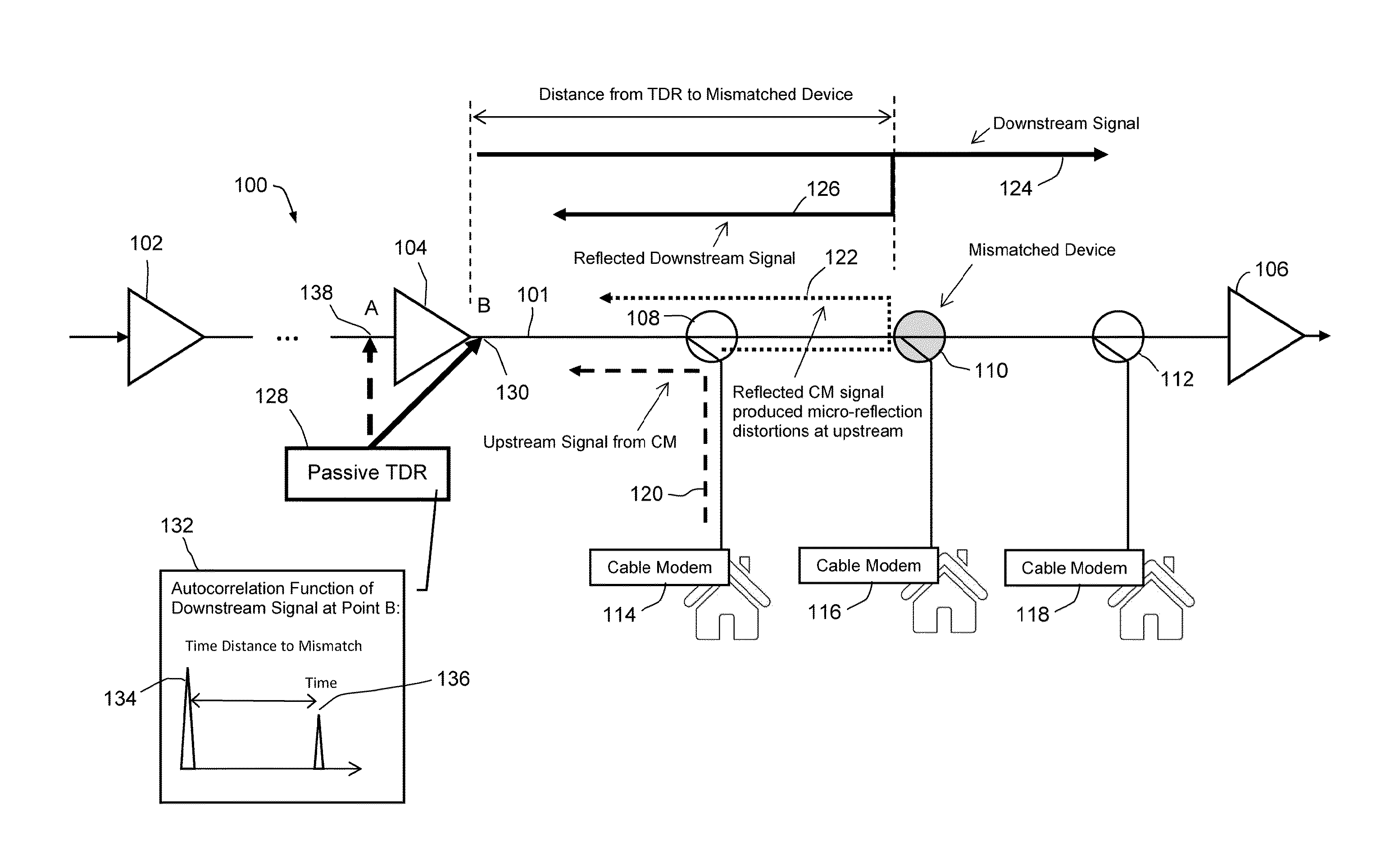
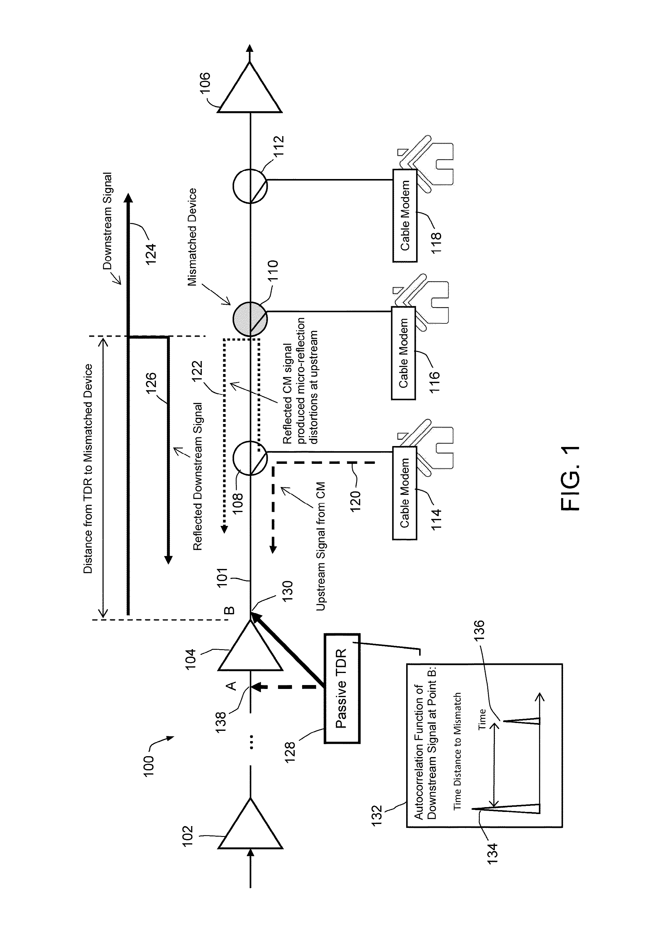
(3) TDR is generally used in a section of a coaxial plant that contains only passive network devices (“passive section”), e.g., between adjacent line or
trunk amplifiers. Downstream signals passing through an
amplifier may already contain reflected signals which could, in an autocorrelation function,
mask echo spikes of impairments located in the passive section under test and create false detections (see FIG. 10). Even random signals, which would theoretically produce Dirac autocorrelation functions, may have extra, undesired peaks and sidelobes in their autocorrelation functions after passing through branches of the HFC network with cascaded amplifiers. These extra peaks and sidelobes may interfere with desired measurements.
As a result of the above-discussed problems, it has been a challenge to attempt a low-cost, low power-consuming implementation of a passive TDR
system for an HFC
cable television network.

