
Data storage device, apparatus and method for using same

a data storage and data technology, applied in the field of portable storage devices or portable cards, can solve the problems of inability to accept the error rate of the disk drive, the medium layer is very thin and fragile, and the head(s) that perform the read/write operation can indent, mark or damage the medium, etc., and achieve the effect of substantially greater memory capacity and freely handling

Inactive Publication Date: 2016-08-30
ULTRACARD
View PDF348 Cites 2 Cited by
  • Summary
  • Abstract
  • Description
  • Claims
  • Application Information

AI Technical Summary

Benefits of technology

The solution provides a portable card with enhanced storage capacity and durability, capable of withstanding rough handling and environmental stresses, while maintaining data integrity and allowing for cleaning and protection against stray magnetic fields.

Problems solved by technology

Contamination or damage to the medium will cause an unacceptable error rate for the disk drive.
The magnetic head(s) that perform the read / write operations can indent, mark or damage the medium through shock, vibration or improper head / medium design.
The medium layers are very thin and fragile, on the order of a few microinches thick, and can be easily destroyed by mechanical damage imposed by the head.
Non-operating environmental conditions, such as those normally found outside a clean room or outside a disk drive, can also easily render the medium unusable.
(a) Moisture, which can cause the Cobalt in the high coercive force magnetic layer to corrode which causes the medium surface to flake off or pit and compromise medium performance;
(b) Chemical contamination from out gassing of internal head / disk assembly components such as uncured epoxy and plasticizers from gaskets, and such chemical contamination can cause the head to stick to the media surface resulting in stopping the drive from spinning or causing a head / disk crash resulting in substantial loss of data;
(c) Particles inside the drive which can cause a head crash that can damage the medium beyond use;
(d) Handling damage by the disk or drive manufacturer including finger prints, scratches, and indentations which can cause nonreversible loss of data;
(e) Shock and vibration from improper drive design or use can cause a head crash that damages the medium beyond use; and
(f) Poorly designed drives can fail during drive power up cycles due to high stiction, friction, temperature / humidity conditions or improper lubricant conditions.
A hard disk drive medium has no direct means to prevent demagnetization by stray magnetic fields should the drive medium be exposed to a stray field having sufficient magnetic field strength to erase the recorded data.
Further, no surface of hard disk drive medium readily permits cleaning, and there are no known commercial hard disk drives that provide a means to clean the medium.
For example, fingerprints cannot easily be removed from the surface of a hard disk drive medium.
Further, any attempts to use a hard disk drive magnetic medium outside of its intended clean and protected environment has been unsuccessful for a number of reasons, such as those discussed above.
The magnetic disk media in known rigid disk drives are not designed to withstand even the most minor surface damage or degradation.
Thinner substrates are desirable in order to be able to package more disks in the disk drive but have the problem of mechanical flutter, especially at high RPM.
A large bend radius of 20 inches will result in permanent deformation of the disk.
A bend radius of less than 20 inches will result in permanent deformation as well as fracturing of the thick Nickel Phosphor layer.
This fracturing of the Nickel Phosphor will propagate through the high coercivity magnetic layer rendering the media useless as a storage device.
The known prior art media used for disk drive including the unabradable, thin protective coatings are not capable of being used in such portable cards.

Method used


Image

  • Data storage device, apparatus and method for using same
  • Data storage device, apparatus and method for using same
  • Data storage device, apparatus and method for using same

Examples


Embodiment Construction

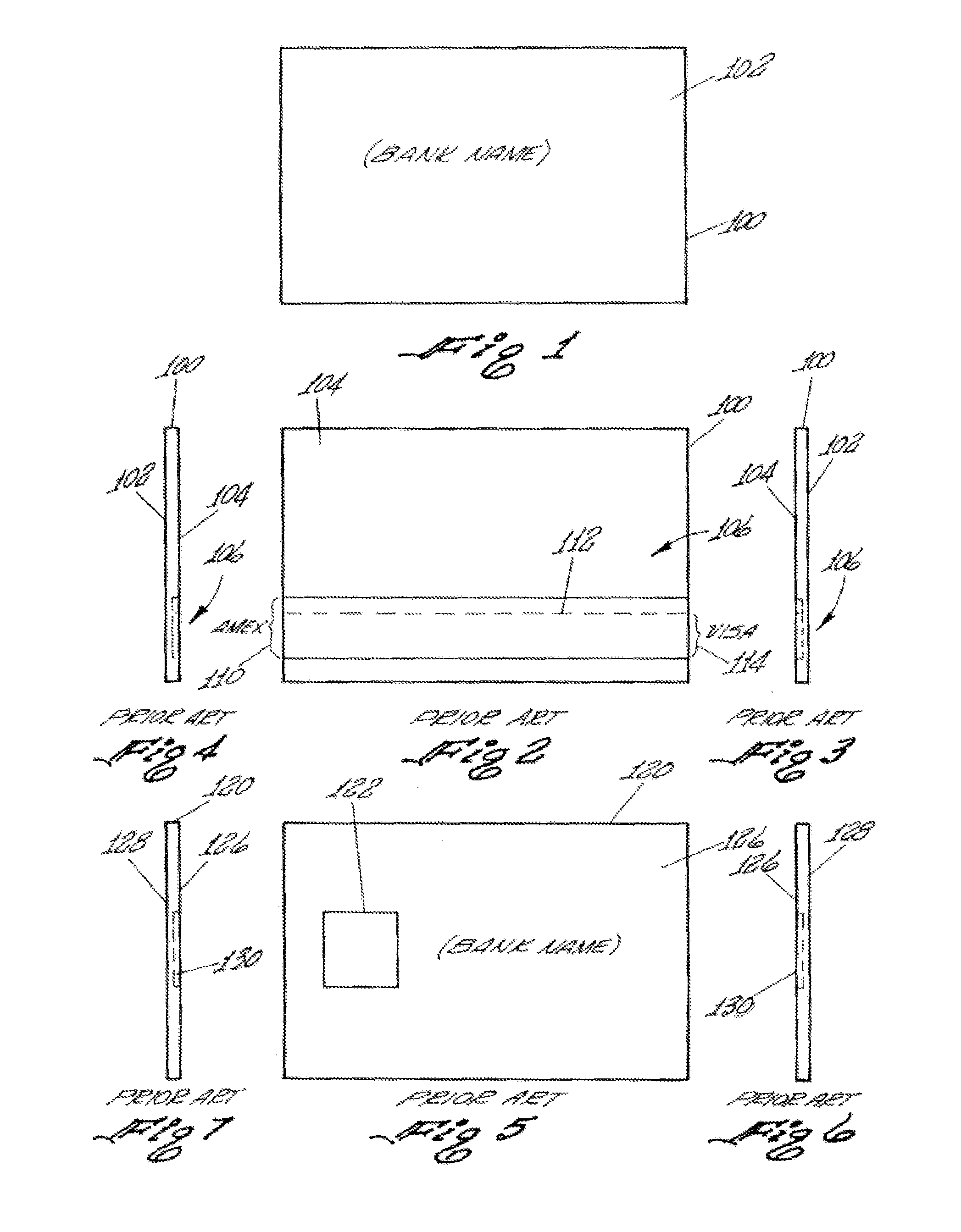
[0143]In this regard, FIGS. 1 through 7, labeled prior art, pictorially illustrate the presently used financial or credit cards. FIGS. 1 through 4 illustrate a credit card 100 where the obverse side 102 bears indicia describing certain bank / user information while the converse side 104, is illustrated in FIG. 2, includes a data storage section 106 which may be in the form of wide magnetic stripe area 110, which is typical of the magnetic stripe area used in a AMEX® credit card, which contains stored data in compliance with the AHSI Standards as described above.

[0144]Alternatively, the magnetic stripe area may be a thin magnetic strip area as depicted by dashed line 112 which forming a narrow stripe 114 which is typically used in a VISA® credit card.

[0145]FIGS. 5 through 7 illustrate a typical Smart Card 120 having an integrated circuit shown as 122 located on the obverse side 126 thereof. The integrated circuit 122 may include a dedicated storage member. The converse side 128 of the ...


PUM

PropertyMeasurementUnit
outer diameteraaaaaaaaaa

Abstract

A data storage device serving as a portable card, magnetically encodeable card, or a magnetic credit card is shown. The data storage device includes a substrate having at least one surface. A high density, magnetically coercive material layer is disposed on or is deposited on the substrate for storing magnetic signals. The magnetically coercive material may have an axis of magnetization that is oriented in a predetermined direction relative to the at least one surface of the substrate. A layer of non-magnetically material is disposed on the substrate for defining an exchange break layer. A relatively hard, abradeable protective coating is formed on the magnetic material layer and has a thickness between a maximum thickness that materially attenuates magnetic signals passing between the magnetic material layer and a transducer and a minimum thickness enabling the protective coating to be abraded by usage in an ambient natural atmosphere operating environment.

Description

RELATED APPLICATIONS[0001]This application is a divisional of U.S. patent application Ser. No. 09 / 693,271 filed Oct. 20, 2000, now U.S. Pat. No. 8,397,998, which claims the benefit, under Title 35, United States Code §119(e), of U.S. Provisional Patent Application Ser. No. 60 / 161,302 filed Oct. 23, 1999.BACKGROUND OF THE INVENTION[0002]1. Field of the Invention[0003]This invention relates generally to data storage devices and more particularly to a portable storage device or a portable card incorporating a data storage device which is capable of having information recorded into and read from the data storage device. The portable storage device or portable card may be in the form of an encodeable card having a magnetic or optical data storage device adapted to be used as a credit card, medical identification card, identification card or the like.[0004]The data storage device utilizes a recording medium or a data storage medium formed on a substrate capable of reliable data recording ...

Claims


Application Information

Patent Timeline
Patent Type & Authority Patents(United States)
IPC IPC(8): G11B5/80G06K19/06G06K7/14G06K7/08G11B5/008G11B7/0033G11B7/085G11B25/04B61C17/00
CPCG06K7/084G06K7/14G11B7/0033G11B25/04G06K19/06196G11B5/00808G11B5/80G11B7/0857G11B7/08576Y10T29/49069
Inventor MANN, DONALD C.COOK, JR., BERT D.
Owner ULTRACARD
Learn More