
Bonding wire and method for manufacturing same

a technology of bonding wire and wire, which is applied in the direction of soldering apparatus, semiconductor/solid-state device details, manufacturing tools, etc., can solve the problems of low reliability, conduction failure, and weak moisture resistance under the aforementioned condition

Active Publication Date: 2016-09-06
NIPPON MICROMETAL CO LTD
View PDF10 Cites 0 Cited by
  • Summary
  • Abstract
  • Description
  • Claims
  • Application Information

AI Technical Summary

Benefits of technology

[0011]Further, it has been assumed that the reason for the palladium film to melt into the ball is partially because a melting time is long and the palladium film thereby melts significantly. It is also assumed that the palladium film can be prevented from melting by rapidly cooling the ball that has been formed and thereby maintaining the original structure of a bonding wire.
[0012]Here, it is an object of the present invention to provide a bonding wire capable of restricting a palladium film from melting at the time of forming a ball; increasing a sphericity of the shape of a ball formed with a palladium-coated copper bonding wire; restricting copper from being exposed on a surface of a ball formed through discharge under nitrogen containing hydrogen at a ratio of 4 to 5 Vol %; and exhibiting a favorable HAST reliability when subjected to a humidity, and a method for manufacturing the same.
[0018]The present invention makes it possible to appropriately maintain a structure and configuration of a bonding wire at the time of performing wire bonding.

Problems solved by technology

However, since only one side of a substrate is to be encapsulated by resin when performing QFN (Quad Flat No-lead) or BGA (Plastic Ball Grid Array) packaging using a palladium-coated copper bonding wire, a weak moisture resistance is exhibited.
According to the studies conducted by the inventors and others, it is now clear that when copper is exposed at a ball-bonded portion, a significant corrosion occurs in a ball-bonded interface of the aluminum pad such that a conduction failure occurs due to an oxidation of aluminum.
However, as for a palladium-coated copper wire, it has been found that a low reliability is exhibited under the aforementioned condition.
It has been assumed that when heating the wire front end with a plasma arc under the mixed gas atmosphere of nitrogen containing hydrogen at the ratio of 4 to 5 Vol %, a plasma temperature tends to be higher than that when heated under a 100% nitrogen gas atmosphere containing no hydrogen, thereby causing a melting point of palladium to decrease when alloyed with copper, thus leading to appearance defects of the ball as, for example, the palladium film melts into the copper ball; copper is exposed on the ball surface due to the palladium film partially melted; or an uneven portion is formed on the ball surface, whereby an bondability deteriorates and a HAST reliability decreases due to a galvanic corrosion of copper.

Method used

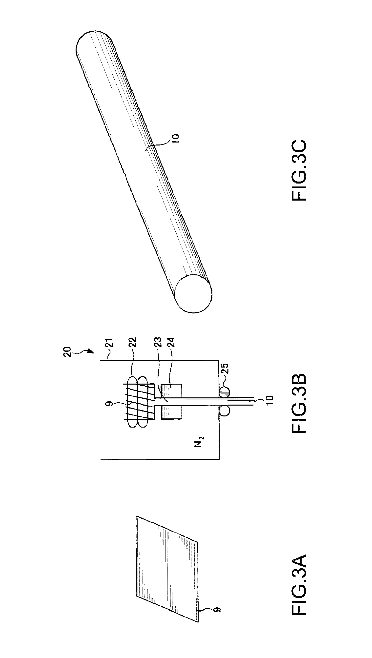

Image

  • Bonding wire and method for manufacturing same
  • Bonding wire and method for manufacturing same
  • Bonding wire and method for manufacturing same

Examples


working example

[0071]Next, bonding wires of working examples of the invention and manufacturing methods thereof are described by comparison with comparative examples.

[0072]Table 1 shows bonding wires of working examples 1 to 11 of the invention and manufacturing methods thereof; and bonding wires of comparative examples 1 to 11 and manufacturing methods thereof.

[0073]

TABLE 1DiameterDiametershrinkageshrinkagerate %Heatrate %CoreRate oftreatment 1Rate ofDiameterThicknessThicknessFinalmemberreductionWirereductionof platedof Pdof AuwirePurity ofin areadiameterin areawireplatingplatingdiametercopper~96%1 mm~99.9%μmμmμmμmWorking14N7No performed124441.02018example24N7No performed121990.4601834N10Performed101990.4601846N7Performed121990.4601556N10No performed121990.4601866N7Performed124441.0201576N7No performed124501.030.0261886N7Performed124501.030.0261896N7Performed124501.030.02620106N7Performed124501.030.02623116N7Performed124501.030.02625Comparative14N18No performed124441.02018example24N18No performed...


PUM

PropertyMeasurementUnit
diameteraaaaaaaaaa
diameteraaaaaaaaaa
diameteraaaaaaaaaa

Abstract

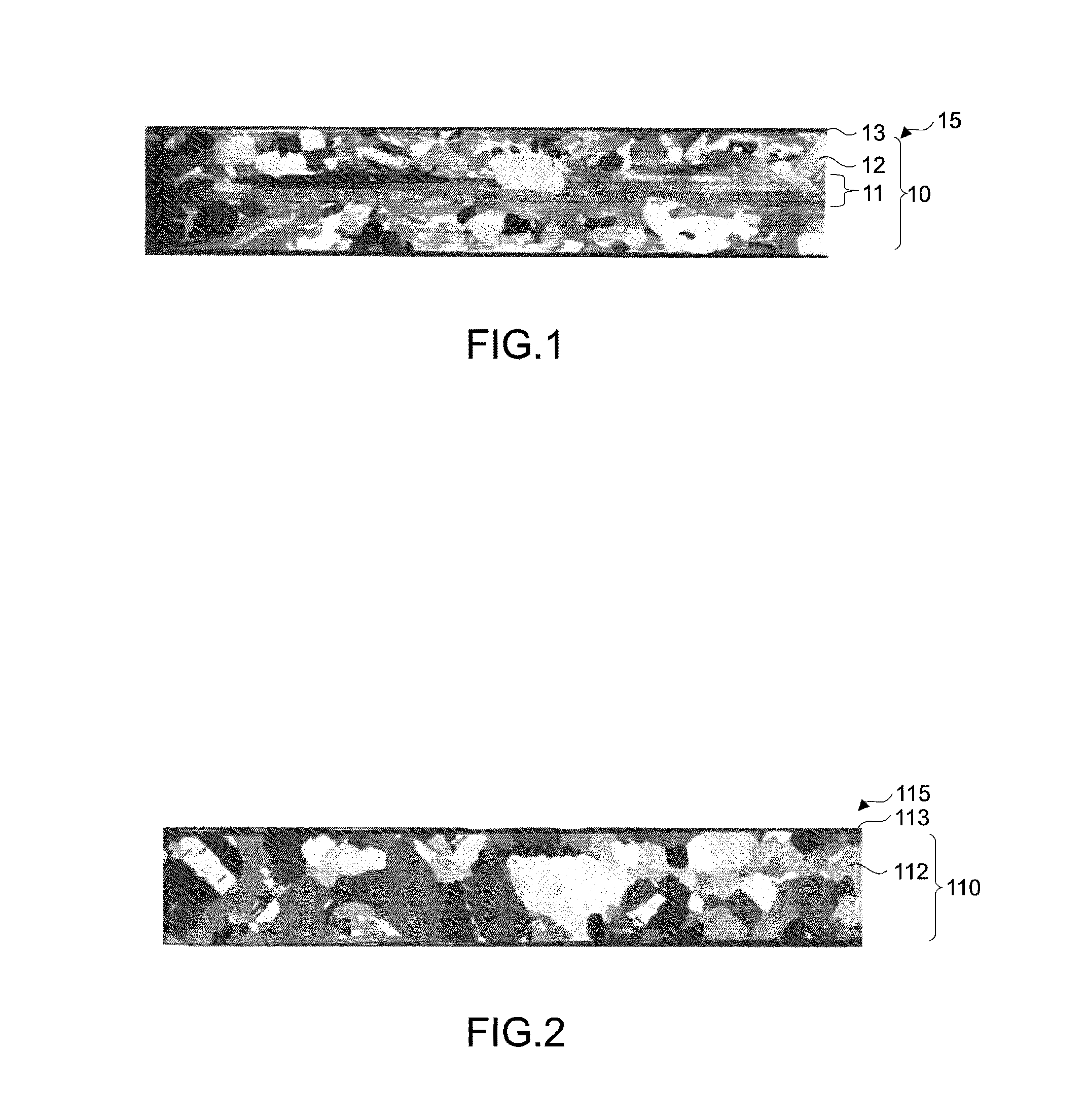
It is an object of the present invention to provide a bonding wire capable of maintaining a structure and a configuration thereof at the time of performing wire bonding; and a manufacturing method thereof. Provided is a bonding wire having a core member mainly composed of copper; and a palladium coating layer. Particularly, formed in a center of the core member is a fibrous structure with copper crystals extending in an axial direction.

Description

CROSS-REFERENCE TO RELATED APPLICATIONS[0001]The present application is a continuation application of International Application No. PCT / JP2013 / 050625, filed Jan. 16, 2013, which claims priority to Japanese Patent Application No. 2012-012778, filed Jan. 25, 2012. The contents of these applications are incorporated herein by reference in their entirety.BACKGROUND OF THE INVENTION[0002]1. Field of the Invention[0003]The present invention relates to a bonding wire and a method for manufacturing the same. Particularly, the present invention relates to a bonding wire having a core member mainly composed of copper; and a palladium coating layer or a coating layer of palladium and gold, and a method for manufacturing the same.[0004]2. Description of Related Art[0005]Conventionally, there has been known a palladium-coated copper bonding wire (e.g. Japanese Patent No. 4158928) obtained by coating a core member mainly composed of copper with palladium.[0006]A palladium-coated copper bonding wi...

Claims


Application Information

Patent Timeline
Patent Type & Authority Patents(United States)
IPC IPC(8): B21C37/04H01L23/00B23K35/30B32B15/01C22C9/00B21C1/02B21C9/00B23K35/22B23K35/40B23K35/02C22F1/00C22F1/08B22D11/041
CPCB23K35/0227B21C1/02B21C9/00B21C37/042B23K35/22B23K35/302B23K35/404B32B15/018C22C9/00C22F1/00C22F1/08H01L24/43H01L24/45H01L24/745B22D11/041H01L2224/43H01L2224/4321H01L2224/43125H01L2224/43848H01L2224/43986H01L2224/45015H01L2224/45147H01L2224/45565H01L2224/45572H01L2224/45644H01L2224/45664H01L2224/745H01L2924/00014H01L2924/01006H01L2924/01015Y10T29/49988Y10T428/12222H01L2924/00011H01L2924/00H01L2224/48H01L2924/01206H01L2924/01204H01L2924/013H01L2924/01079H01L2924/01046H01L2924/01005H01L2924/01033
Inventor TOGASHI, RYO
Owner NIPPON MICROMETAL CO LTD
Learn More