
Self-adjusting power supply circuit of silicon controlled dimming in LED lighting

a technology of led lighting and power supply circuit, which is applied in the direction of electric variable regulation, process and machine control, instruments, etc., can solve the problems of power supply, power consumption will be enormously high, power supply becomes a very difficult condition to maintain, etc., and achieves simple peripheral configuration, high degree of integration, good manufacturability

Active Publication Date: 2017-02-21
SHENZHEN WINSEMI MICROELECTRONICS
View PDF2 Cites 16 Cited by
  • Summary
  • Abstract
  • Description
  • Claims
  • Application Information

AI Technical Summary

Benefits of technology

The present invention provides a self-adjusting power supply circuit for silicon controlled dimming in LED lighting. This circuit is suitable for high integration and has simple peripherals. It is highly manufacturable, has low manufacturing cost, high power supply efficiency and little wastage. This circuit has progressive effects in optimizing power supply and improving the performance of LED lighting.

Problems solved by technology

In such situation, power supply becomes a very difficult condition to maintain when electrical level is zero for most of the time.
If power supply is insufficient, the drive chip will restart and the LED light will flash as a result.
As noted above, power supply is a very important technical issue in a silicon controlled dimming circuit.
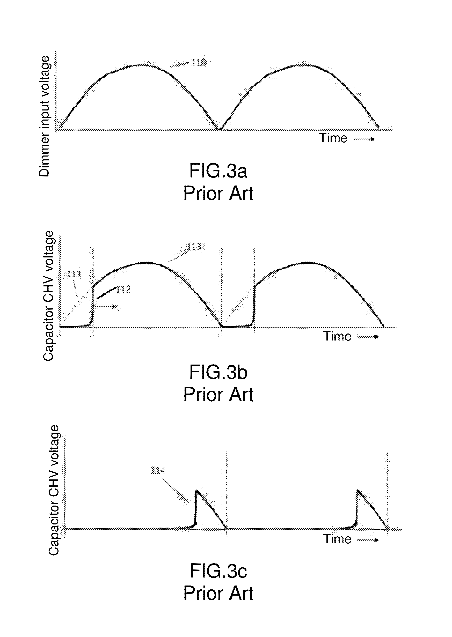
The greatest disadvantage of this technology is that the eleventh resistor R11 has to allow current of small enough voltage to pass through so as to allow power supply even under the voltage represented by the fourth waveform 114 shown in FIG. 3c, but when the waveform is near to its full cycle, power consumption will be enormously high (wasted through direct grounding of a first clamp tube Z1), and there is a great loss of efficiency.
However, its greatest disadvantage is that the drive chip has to be designed in accordance with high-voltage BCD.
High-voltage BCD has a much higher cost and the space required by each component is larger.
Another deadly disadvantage is that, under high-voltage BCD, ESD of the JFET is not good, and thus resulting in easy damage of chip pins and lowered overall product yield rate along with complaints from the customers.
The third one having a common ground structure (FIG. 6) has disadvantages of requiring additional windings and a network formed by high-voltage diode, high-voltage capacitors and resistors for power supply.
The large quantity of components increases the cost and complicates the wire arrangement on a PCB.
In actual use, it is discovered that in order to adapt to different dimmers, RC network has to be more complicated to solve the problem of power supply.
Besides, as shown in FIGS. 6-7, the second clamp diode Z2 and the third clamp diode Z3 are used for consuming the extra power at the VCC terminal, thereby increasing power consumption and lowering efficiency.

Method used


Image

  • Self-adjusting power supply circuit of silicon controlled dimming in LED lighting
  • Self-adjusting power supply circuit of silicon controlled dimming in LED lighting
  • Self-adjusting power supply circuit of silicon controlled dimming in LED lighting

Examples


Embodiment Construction

[0027]A preferred embodiment of the present invention is described below to explain in detail the technical solution of the present invention.

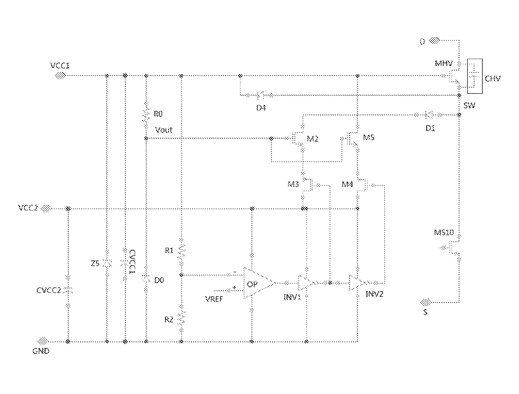
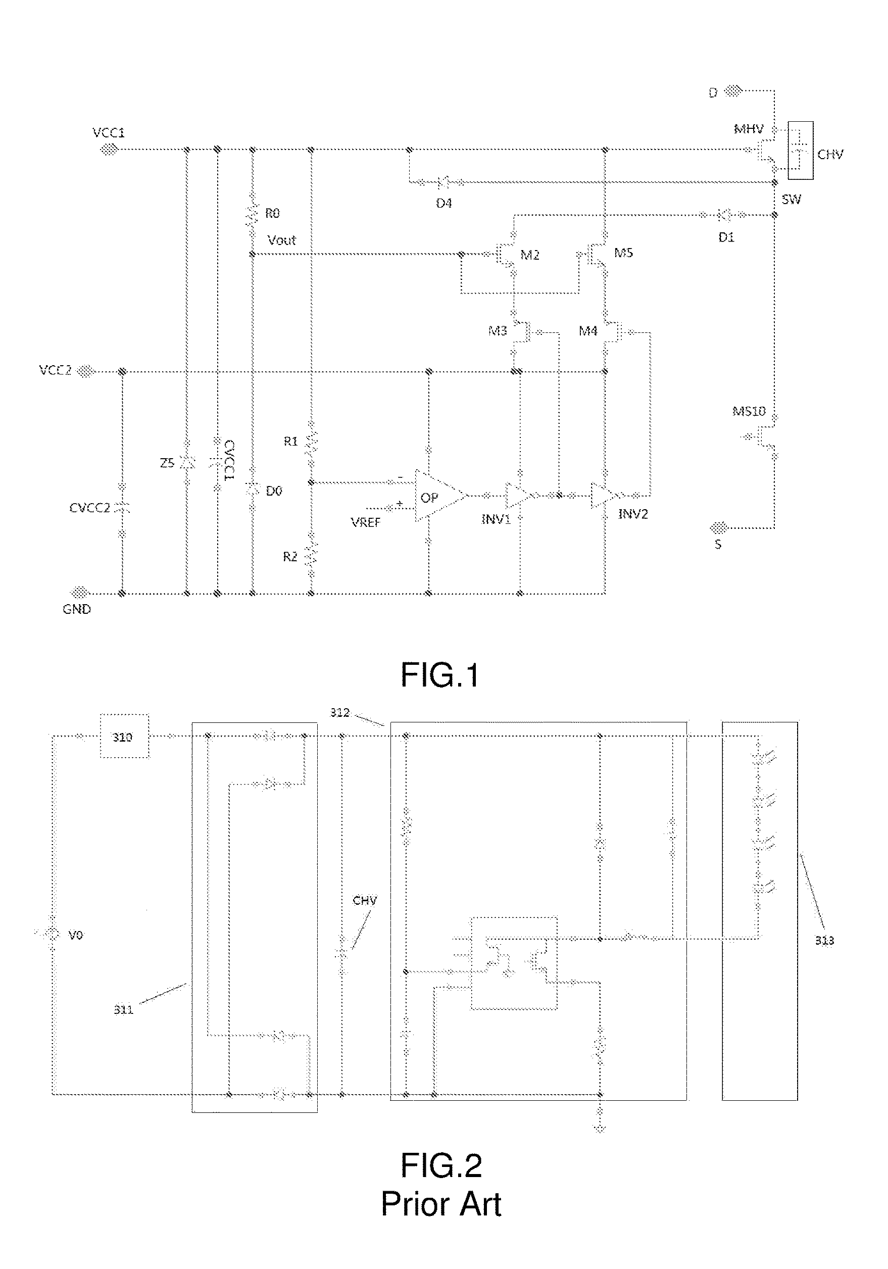
[0028]As shown in FIG. 1, a self-adjusting power supply circuit of silicon controlled dimming in LED lighting according to the present invention comprises a first resistor R0, a second resistor R1, a third resistor R2, a first diode D0, a second diode D1, a third diode D4, a fourth diode Z5, a comparator OP, a first invertor INV1, a second invertor INV2, a first field effect transistor M2, a second field effect transistor M3, a third field effect transistor M4, a fourth field effect transistor M5, a switch transistor MS10, a fifth field effect transistor MHV, and a parasitic capacitor CHV. The first resistor R0 and the first diode D0 are connected in series. The fourth diode Z5 is connected in parallel with the first resistor R0 and the first diode D0. The first resistor R0 is connected in parallel with the second resistor R1. The second resis...


PUM


Abstract

A self-adjusting power supply circuit of silicon controlled dimming in LED lighting, having a first resistor, a second resistor, a third resistor, a first diode, a second diode, a third diode, a fourth diode, a comparator, a first invertor, a second invertor, a first field effect transistor, a second field effect transistor, a third field effect transistor, a fourth field effect transistor, a switch transistor, a fifth field effect transistor, and a parasitic capacitor; the first resistor and the first diode are connected in series; the fourth diode is connected in parallel with the first resistor and the first diode; the second resistor and the third resistor are connected in series; two pins of the first invertor are connected respectively with the comparator and the second invertor; the first field effect transistor is connected in series with the second field effect transistor and the second diode; the third field effect transistor is connected in series with the fourth field effect transistor; the third diode is connected in parallel with the fifth field effect transistor; the fifth field effect transistor is connected in parallel with the parasitic capacitor; the fifth field effect transistor is connected in series with the switch transistor.

Description

BACKGROUND OF THE INVENTION[0001]The present invention relates to a power supply circuit, and more specifically relates to a self-adjusting power supply circuit of silicon controlled dimming in LED lighting.[0002]Silicon controlled dimming is a lighting adjustment method commonly applied to incandescent lights and energy-saving lights. In recent years, due to the developments of LED lighting technology, silicon controlled dimming technology is also applied to LED lights, and now widely applied to technical fields such as household and commercial lightings. FIG. 2 schematically illustrates a circuit diagram of silicon controlled dimming in LED lighting. V0 represents AC mains voltage, which is generally 220 VAC or 120 VAC; reference number 310 represents a silicon controlled dimmer; reference 311 represents a rectifier bridge; reference number 312 represents buck switching power supply; and reference 313 represents a load which is an LED light. When the complete AC mains voltage is c...

Claims


Application Information

Patent Timeline
Patent Type & Authority Patents(United States)
IPC IPC(8): G05F1/00H05B37/02H05B39/04H05B41/36H05B33/08H05B44/00
CPCH05B33/0845H05B33/0809Y02B20/30H05B45/37H05B45/10H05B45/395
Inventor LAI, LIANZHANGWANG, MUHONGTAO, JIFENGSUN, ZHONGHUACHEN, WEILIN
Owner SHENZHEN WINSEMI MICROELECTRONICS
Learn More