
Process for making paper and nonwoven articles comprising synthetic microfiber binders

a technology of synthetic fibers and binders, which is applied in the field of paper and nonwoven articles comprising synthetic fibers, can solve the problems of web sticking to high temperature drying, current binder fibers suffering, and typically be rather large (approximately 10-20 microns)

Inactive Publication Date: 2017-04-11
EASTMAN CHEM CO
View PDF888 Cites 37 Cited by
  • Summary
  • Abstract
  • Description
  • Claims
  • Application Information

AI Technical Summary

Benefits of technology

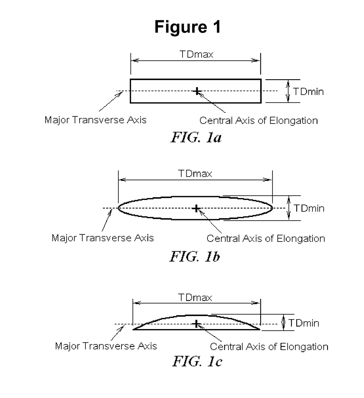
The present invention relates to a paper or nonwoven article comprising a nonwoven web layer consisting of fibers and binder microfibers. The binder microfibers have a melting temperature lower than the melting temperature of the fibers and are made of a water non-dispersible, synthetic polymer. The binder microfibers have a length of less than ¼ inch and a fineness of less than 0.5 denier. The binder microfibers are thermally bonded to the fibers at a temperature that melts the surfaces of the binder microfibers without melting the fibers, resulting in a strong bond between the binder microfibers and the fibers. This process can improve the strength and flexibility of the paper or nonwoven article.

Problems solved by technology

While significant strength can be achieved through this method, there are issues which it can create.
Wet-laid nonwovens can often include fibers with wide-ranging wettability to such liquid materials (e.g. cellulosic versus synthetic fibers) such that uniform application of the liquid binder can prove a challenge.
There is not only an energy expenditure required by this process (high heat of vaporization for water) but non-uniform binder levels which may be present at the nonwoven surface can result in sticking of the web to high temperature drying cans which are used in this process
Current binder fibers suffer from the fact that they can typically be rather large (approximately 10-20 microns) compared to other fibrous materials present in the sheet.
This larger size can result in rather significant adverse changes to the pore size / porosity of the nonwoven media.
In addition, monocomponent binder fibers (e.g. polyvinyl alcohol) at these relatively large diameters have low surface-to-volume ratios which can result in the melted polymer flowing and filling nonwoven pores much in the way that liquid binders do.
However, core-sheath binder fibers are still rather large fibers which can significantly increase the average pore size of a nonwoven web.

Method used


Image

  • Process for making paper and nonwoven articles comprising synthetic microfiber binders
  • Process for making paper and nonwoven articles comprising synthetic microfiber binders
  • Process for making paper and nonwoven articles comprising synthetic microfiber binders

Examples


example 1

[0180]A sulfopolyester polymer was prepared with the following diacid and diol composition: diacid composition (69 mole percent terephthalic acid, 22.5 mole percent isophthalic 25 acid, and 8.5 mole percent 5-(sodiosulfo)isophthalic acid) and diol composition (65 mole percent ethylene glycol and 35 mole percent diethylene glycol). The sulfopolyester was prepared by high temperature polyesterification under a vacuum. The esterification conditions were controlled to produce a sulfopolyester having an inherent viscosity of about 0.33. The melt viscosity of this sulfopolyester was measured to be in the range of about 6000 to 7000 poise at 240° C. and 1 rad / sec shear rate.

example 2

[0181]The sulfopolyester polymer of Example 1 was spun into bicomponent islands-in-the-sea cross-section fibers using a bicomponent extrusion line. The primary extruder (A) fed Eastman F61 HC PET polyester to form the “islands” in the islands-in-the-sea cross-section structure. The secondary extruder (B) fed the water dispersible sulfopolyester polymer to form the “sea” in the islands-in-sea bicomponent fiber. The inherent viscosity of the polyester was 0.61 dL / g while the melt viscosity of the dry sulfopolyester was about 7,000 poise measured at 240° C. and 1 rad / sec strain rate using the melt viscosity measurement procedure described previously. The polymer ratio between “islands” polyester and “sea” sulfopolyester was 2.33 to 1. The filaments of the bicomponent fiber were then drawn in line using a set of two godet rolls to provide a filament draw ratio of about 3.3×, thus forming the drawn islands-in-sea bicomponent filaments with a nominal denier per filament of about 5.0. Thes...

example 3

[0182]The sulfopolyester polymer of Example 1 was spun into bicomponent islands-in-the-sea cross-section fibers using a bicomponent extrusion line. The primary extruder (A) fed Eastman F61 HC PET polyester to form the “islands” in the islands-in-the-sea cross-section structure. The secondary extruder (B) fed the water dispersible sulfopolyester polymer to form the “sea” in the islands-in-sea bicomponent fiber. The inherent viscosity of the polyester was 0.61 dL / g while the melt viscosity of the dry sulfopolyester was about 7,000 poise measured at 240° C. and 1 rad / sec strain rate using the melt viscosity measurement procedure described previously. The polymer ratio between “islands” polyester and “sea” sulfopolyester was 2.33 to 1. The filaments of the bicomponent fiber were then drawn in line using a set of two godet rolls to provide a filament draw ratio of about 3.3×. These filaments comprised the polyester microfiber islands having an average diameter of about 5.0 microns. The d...


PUM

PropertyMeasurementUnit
melting pointaaaaaaaaaa
lengthaaaaaaaaaa
melt viscosityaaaaaaaaaa

Abstract

A process of making a paper or nonwoven article is provide. The process comprising:a) providing a fiber furnish comprising a plurality of fibers and a plurality of binder microfibers, wherein the binder microfibers comprise a water non-dispersible, synthetic polymer; wherein the binder microfibers have a length of less than 25 millimeters and a fineness of less than 0.5 d / f; and wherein the binder microfibers have a melting temperature that is less than the melting temperature of the fibers;b) routing the fiber furnish to a wet-laid nonwoven process to produce at least one wet-laid nonwoven web layer;c) removing water from the wet-laid nonwoven web layer; andd) thermally bonding the wet-laid nonwoven web layer after step (c); wherein the thermal bonding is conducted at a temperature such that the surfaces of the binder microfibers at least partially melt without causing the fibers to melt thereby bonding the binder microfibers to the fibers to produce the paper or nonwoven article.

Description

FIELD OF THE INVENTION[0001]The present invention relates to paper and nonwoven articles comprising synthetic binder microfibers. The present invention also relates to the process of making paper and nonwoven articles comprising synthetic microfiber binders.BACKGROUND OF THE INVENTION[0002]In wet-laid nonwovens, it is necessary to bond together the relatively short fibers which constitute the nonwoven in order for the resulting web to have any significant strength. Generally, liquid binders and / or binder fibers are utilized for this purpose. In the case of liquid binders, a polymer solution or dispersion (e.g. latex) is applied to the nonwoven web and subsequently dried. While significant strength can be achieved through this method, there are issues which it can create. The first of these is that the liquid binder requires additional process steps in its application. Specifically, the binder solution / dispersion must be applied in a manner to yield a uniform distribution of the bind...

Claims


Application Information

Patent Timeline
Patent Type & Authority Patents(United States)
IPC IPC(8): D21H13/02D21H13/06D21H13/20D21H15/02D21H13/36D21H13/12
CPCD21H13/02D21H13/06D21H13/12D21H13/20D21H13/36D21H15/02
Inventor CLARK, MARK DWIGHTDEMA, KEHSOHN, SUNGKYUNSMITH, ERNEST PHILLIPANDERSON, CHRIS DELBERTEVERETT, CHARLES STUART
Owner EASTMAN CHEM CO
Learn More