
Mineral material processing plant and a method for operating a processing plant

a technology of processing plant and mineral material, which is applied in the direction of solid separation, grain treatment, chemistry apparatus and processes, etc., can solve the problems of difficult to evenly spread the material on the screen, the conveyor movement mechanism is heavy and expensive, and the feeding end of the plant is required space, etc., to achieve convenient maintenance, shorten the processing plant, and facilitate the effect of maintenan

Active Publication Date: 2017-05-02
METSO OUTOTEC (FINLAND) OY
View PDF10 Cites 2 Cited by
  • Summary
  • Abstract
  • Description
  • Claims
  • Application Information

AI Technical Summary

Benefits of technology

This design enhances serviceability, reliability, and transportability of mineral material processing plants by simplifying the conveyor system, reducing shutdown times, and allowing for broader, more efficient material handling without the need for extra equipment, thus improving overall processing efficiency.

Problems solved by technology

Moving mechanisms used for the moving of the conveyor are heavy and expensive constructions.
The moving of the conveyor away from the crusher requires space at the feeding end of the plant which may be problematic if the plant in question is a mobile crushing plant which is operating in a process of several plants and a feeding machine is close.
The sliding mechanisms tolerate poorly dirty circumstances and are sensitive with respect to production inaccuracy.
Then the process includes an extra wearing part (vibration chute, hopper) and the material arrives to the screen from a side direction wherein spreading of the material evenly on the screen is problematic.
Alternatively the plant must include an expensive, heavy, and often unreliable moving mechanism by which the conveyor can be moved off the crusher for transport and service of the crusher.
Alternatively the conveyor must be lifted by a separate hoist which must be brought beside the plant which is expensive and time consuming.
Expensive and inconvenient mechanisms intended to move the conveyor are left away from the construction.

Method used


Image

  • Mineral material processing plant and a method for operating a processing plant
  • Mineral material processing plant and a method for operating a processing plant
  • Mineral material processing plant and a method for operating a processing plant

Examples


Embodiment Construction

[0062]In the following description, like numbers denote like elements. It should be appreciated that the illustrated drawings are not entirely in scale, and that the drawings mainly serve the purpose of illustrating some example embodiments of the invention.

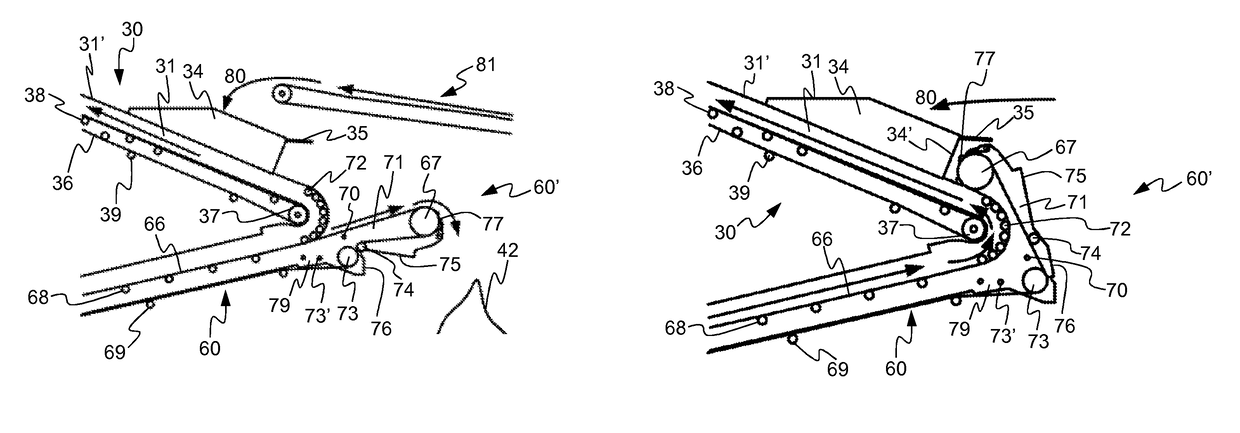
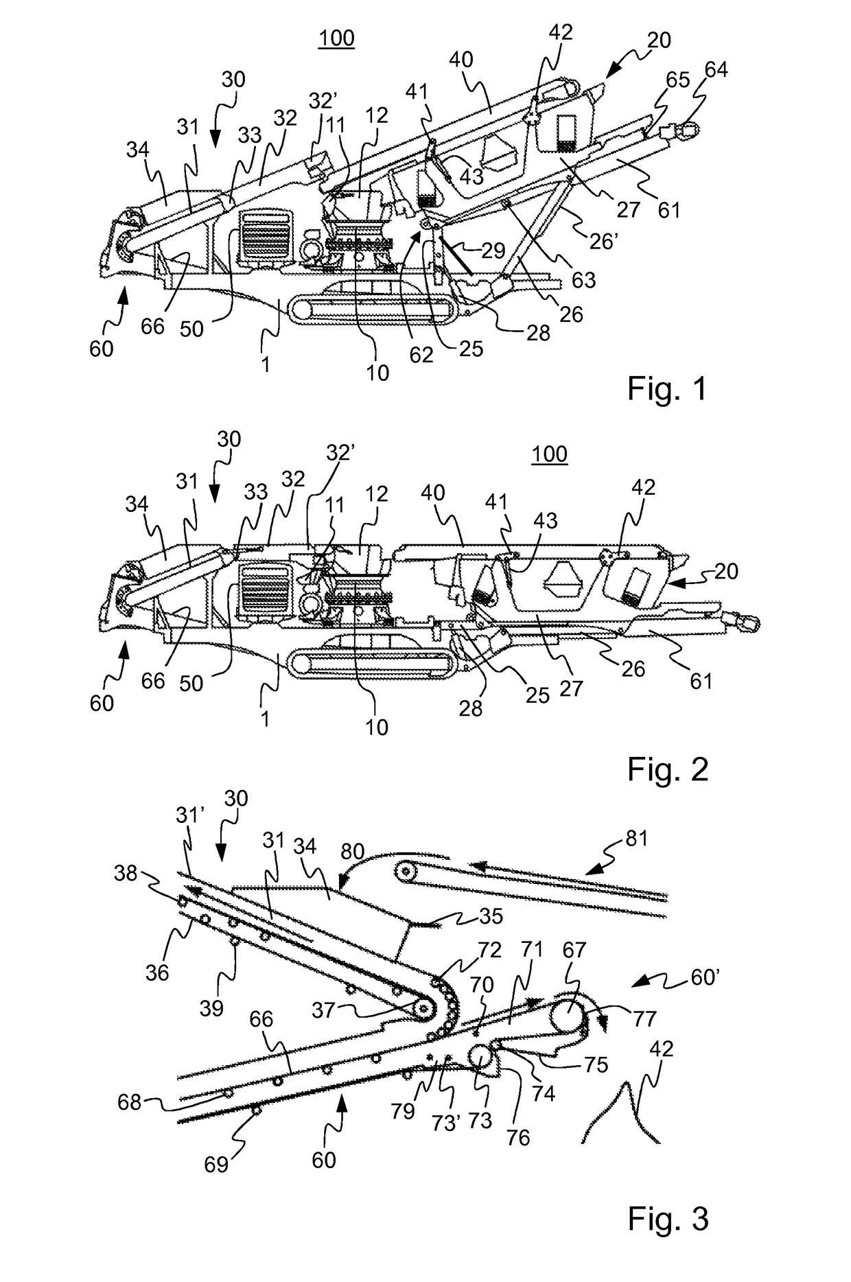
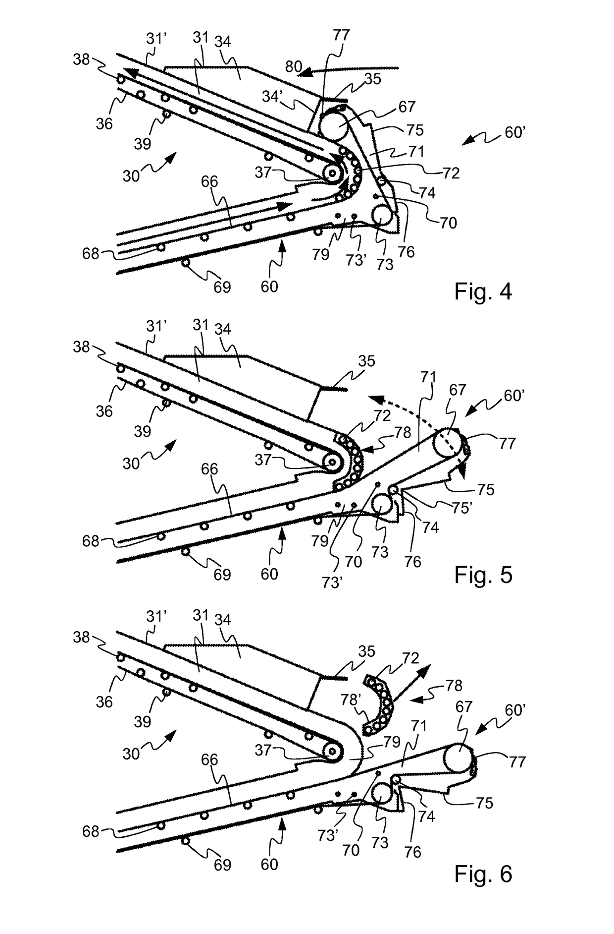
[0063]A mineral material processing plant 100 shown in FIGS. 1 and 2 comprises a frame 1 and a crusher 10 fixed to the frame, a motor module 50, a centrifugal conveyor 60 as a main conveyor, and further a first conveyor 30. Further the plant comprises a second conveyor 40, a screen 20 and a discharge conveyor 61 which are fixed to the frame by support arms which are forming four-bar linkages. The frame 1 comprises in this embodiment further a track base for moving the processing plant. The crusher or the screen, or both simultaneously can be operated in the processing plant 100 as the processing apparatus.

[0064]The centrifugal conveyor receives processed material from the crusher 10 or the screen 20. Material is raised by the cen...


PUM


Abstract

A mineral material processing plant includes a frame; a crusher; a centrifugal conveyor; and a first conveyor; and the centrifugal conveyor includes a first idler drum and a second idler drum and a main conveyor belt surrounding the idler drums, a pivot and a folding head which is pivotable around the pivot; and the folding head includes a movable frame to which the second idler drum is bearing-mounted, to connect the centrifugal conveyor in material transport connection with the first conveyor and away from said material transport connection. A pivot point of the pivot is located in a region inside the circumference of the main conveyor belt. A method for operating a processing plant is also disclosed.

Description

CROSS-REFERENCE TO RELATED APPLICATIONS[0001]This application claims priority to PCT / FI2013 / 050854, filed Sep. 4, 2013, and published in English on Mar. 12, 2015 as publication number WO 2015 / 033012 A1, incorporated herein by reference.TECHNICAL FIELD[0002]The invention relates to mineral material processing. The invention relates particularly, though not exclusively, to conveyor solutions in a mineral material processing plant.BACKGROUND ART[0003]Mineral material, for example rock, is gained from the earth for crushing by exploding or excavating. The rock can also be natural rock and gravel or construction waste. Mobile crushers and stationary crushing applications are used in crushing. An excavator or wheeled loader loads the material to be crushed into the crusher's feed hopper from where the material to be crushed may fall in a jaw of a crusher or a feeder moves the rock material towards the crusher. The material to be crushed may also be recyclable material such as concrete, br...

Claims


Application Information

Patent Timeline
Patent Type & Authority Patents(United States)
IPC IPC(8): B02C21/02B07B1/00B65G21/10B65G41/00B02C23/08
CPCB02C21/02B02C23/08B07B1/005B65G21/10B65G41/002
Inventor SALMINEN, VESA-MATTIHULTTINEN, JOUNI
Owner METSO OUTOTEC (FINLAND) OY
Learn More