2-dimensional fiber array structure

a fiber array and two-dimensional technology, applied in the field of two-dimensional fiber array structure, can solve the problems of difficult parallelism between two ends of glass baseboard a, high cost in keeping accuracy of fiber array and low yield rate, and limited pitch between two adjacent layers of fibers b, etc., to achieve accurate separation, reduce the tolerance along the x axis, and accurately separate the baseboard

Active Publication Date: 2017-07-18
ALLIAN FIBER OPTIC PROD INC
View PDF9 Cites 23 Cited by
  • Summary
  • Abstract
  • Description
  • Claims
  • Application Information

AI Technical Summary

Benefits of technology

[0011]An objective of the present disclosure is to provide a two-dimensional fiber array structure including a base, the base includes a baseboard and a cover board disposed above the baseboard, each of the baseboard and the cover board includes at least one first groove recessed on an abutment surface thereof along Z axis, and a plurality of second grooves respectively recessed at two external sides of the first grooves, and the abutment surfaces of the baseboard and the cover board face to each other, and the plurality of second grooves of the baseboard correspond in position to that of the cover board. A plurality of first fiber cores of the optical fiber cable are respectively positioned in the first grooves to form an array of the fiber layers. The second fiber cores of the positioning fibers are respectively positioned in the two second grooves of the base to accurately separate the baseboard from the cover board by predetermined pitch along X axis. A divider or a plurality of third fiber cores of the spacer layer are abutted with the first fiber cores of the two adjacent fiber layers to more accurately separate the two adjacent fiber layers from each other by predetermined pitch along Y axis, so that the position tolerance along X axis becomes smaller and the accuracy is improved. The second fiber core and the third fiber core have diameters of given specification, so that the accuracy can be consistent, and the two-dimensional fiber array structure can be directly used without extra precise machining. Therefore, the two-dimensional fiber array structure of the present disclosure can have higher process yield and is suitable for mass production, so as to further effectively save production cost and ensure the quality and stability of transmitting the optical signal.
[0012]Other objective of the present disclosure is that the second fiber cores of the positioning fibers are positioned in the second grooves located at different positions on the base, so that the baseboard and the cover board can be accurately separated from each other by predetermined pitch along X axis, and the plurality of third fiber cores having predetermined diameter or the divider having predetermined thickness can be used to separate the two adjacent fiber layers by predetermined pitch. During machining process, the plurality of first grooves of the base may have tolerances, and when the number of the fiber layers or the first fiber cores of the optical fiber cable is increased, the position tolerance along X axis may be reduced because the plurality of third fiber cores or the divider of the spacer layer more accurately separate the two adjacent fiber layers from each other, whereby the dimension and position accuracy of the fiber array product can be improved, and the loss of light can be reduced to further improve the quality of transmitting optical signal.

Problems solved by technology

In addition, the pitch between the two adjacent layers of the fibers B is limited by the capacity of producing the glass baseboard A and the maximum depth of the V-shaped groove A1.
In fact, it is very difficult to produce the glass baseboard A with a thickness smaller than 0.3 mm, and multiple processes and stack of layers of the glass baseboards A also cause high cost in keeping accuracy of the fiber array and lower yield rate.
In addition, the parallelism between two ends of the glass baseboard A is also not easy to achieve.
Therefore, it is very hard to reproduce the high-end fiber array having the fibers B with high-density and micron-level position accuracy.
However, this technology is only adapted to the fiber array which uses a wafer as the baseboard, and also has disadvantages of complicated wafer process, material limitation and high cost, which results in bottleneck for application, for example, quick mass production and cost reduction cannot be achieved easily, and the process may cause environment pollution and be not environmentally-friendly.
However, after assembly of the baseboard and the plurality of fibers, the epoxy resin is heat-shrinkable or stress-deformable easily to shift fibers, which may result in poor package yield of the fiber array and more insertion loss.
However, the plurality of fibers B are hardly to shift along X or Y axis subject to constraint of the stacked structure, and machining process for the V-shaped grooves A1 and D1 of the glass substrate A and the cover board D may cause tolerance, so the problem of position tolerance and accumulated error are also generated to make the fibers B easily shifted when the stacking number or disposal number of the fibers B is increased, which results in reduction in position accuracy of each of the fibers B of the fiber array.
Moreover, when each of the fibers B has different accuracy, the insertion loss may be increased and the return loss is decreased, thereby impacting quality of transmitting optical signal.

Method used


Image

  • 2-dimensional fiber array structure
  • 2-dimensional fiber array structure
  • 2-dimensional fiber array structure

Examples


Embodiment Construction

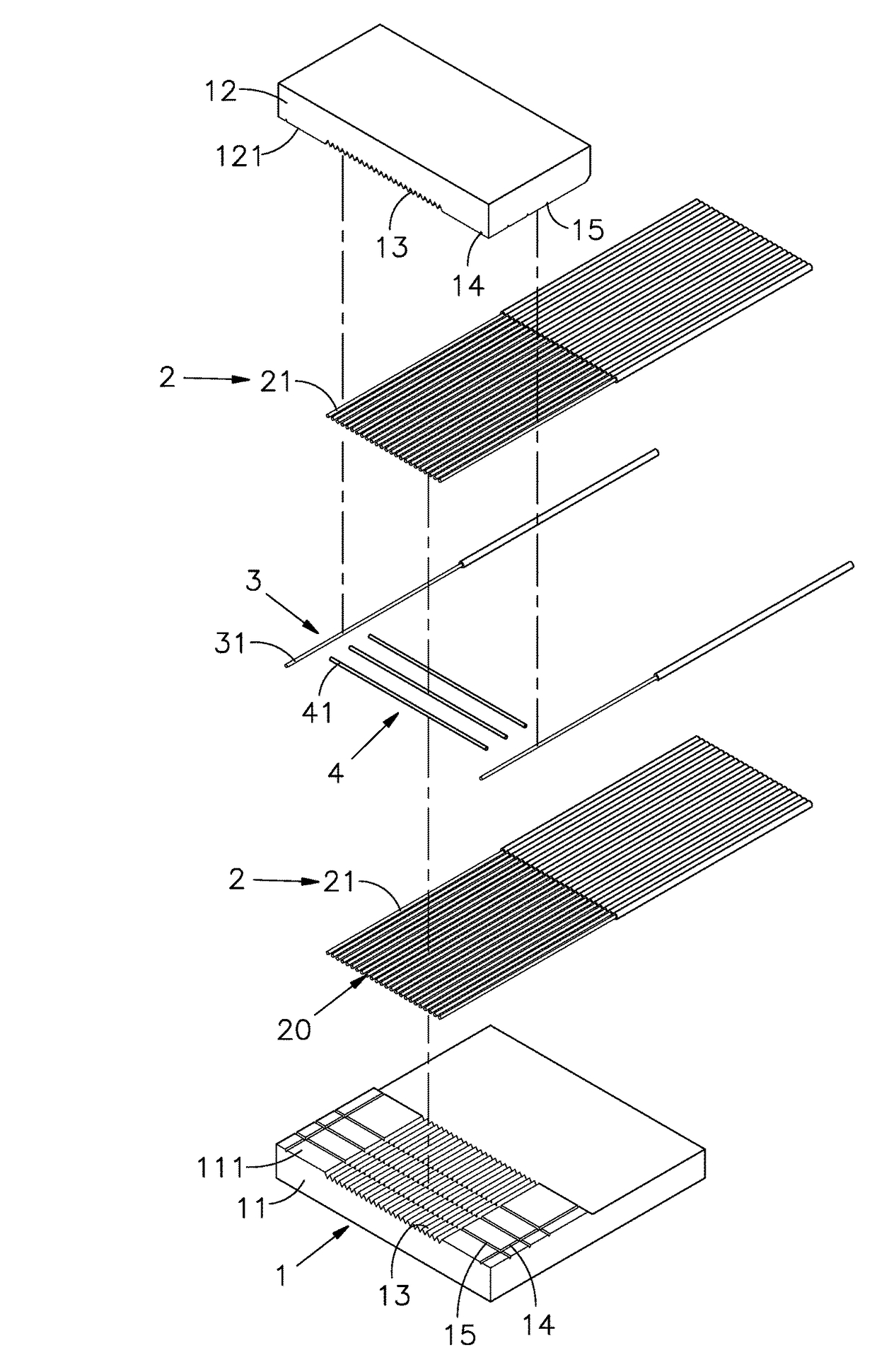
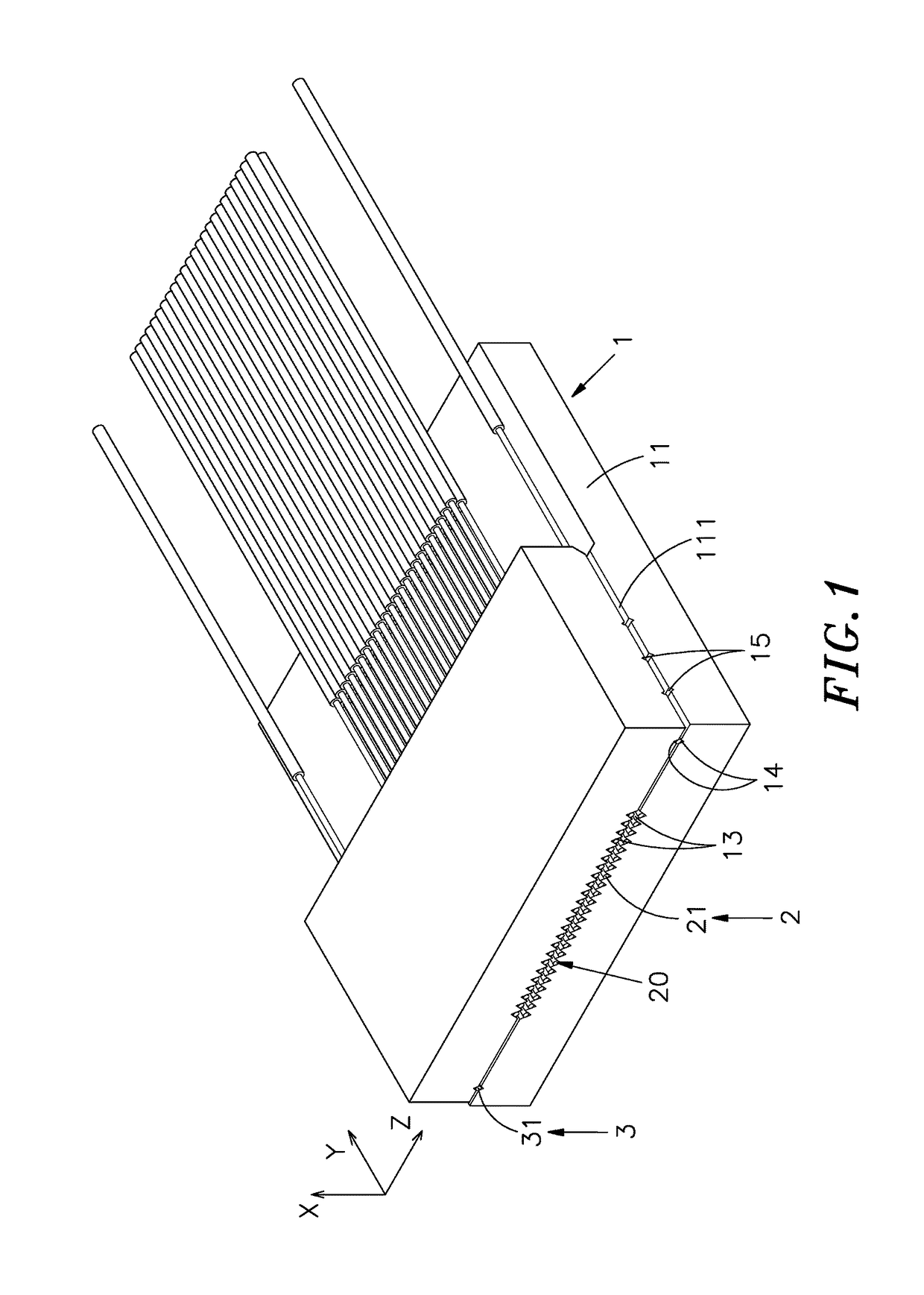
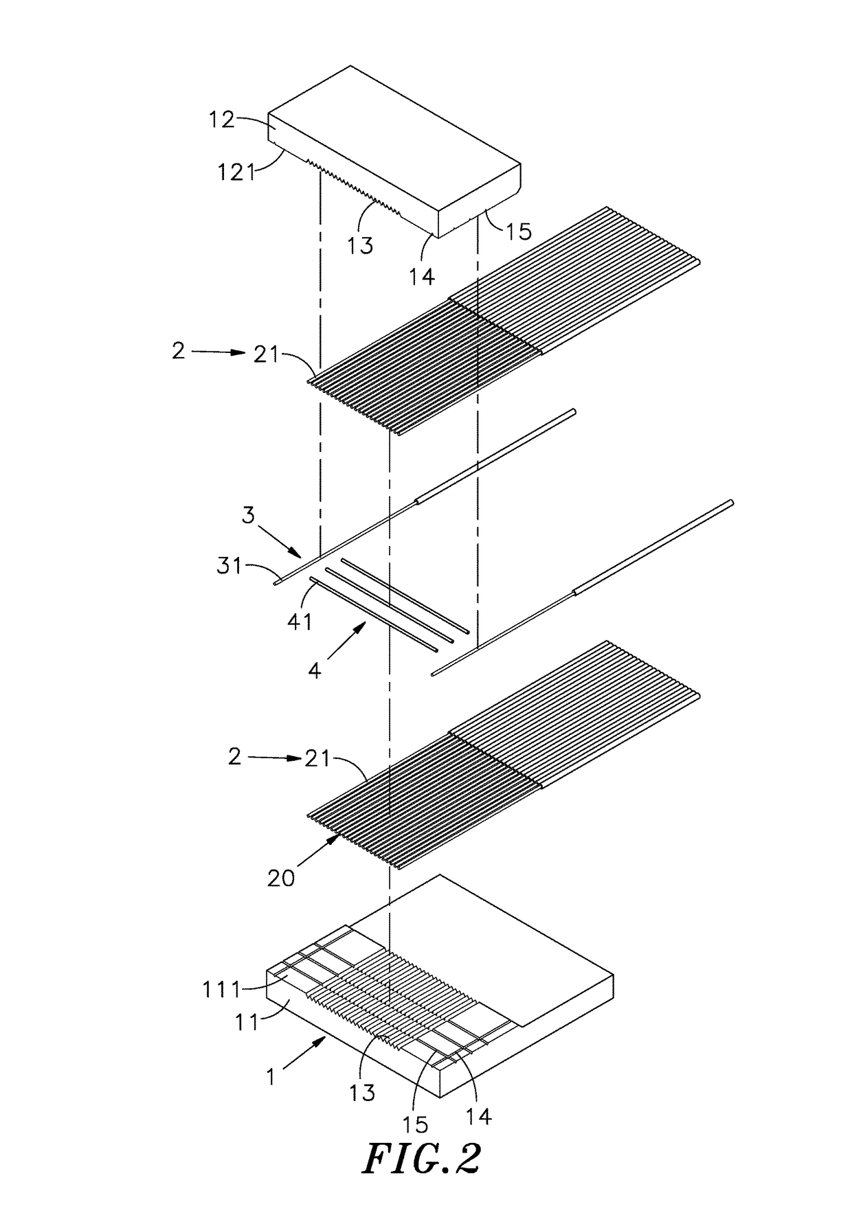
[0026]Reference will now be made in detail to the exemplary embodiments of the present disclosure, examples of which are illustrated in the accompanying drawings. Therefore, it is to be understood that the foregoing is illustrative of exemplary embodiments and is not to be construed as limited to the specific embodiments disclosed, and that modifications to the disclosed exemplary embodiments, as well as other exemplary embodiments, are intended to be included within the scope of the appended claims. These embodiments are provided so that this disclosure will be thorough and complete, and will fully convey the inventive concept to those skilled in the art. The relative proportions and ratios of elements in the drawings may be exaggerated or diminished in size for the sake of clarity and convenience in the drawings, and such arbitrary proportions are only illustrative and not limiting in any way. The same reference numbers are used in the drawings and the description to refer to the ...


PUM


Abstract

The present disclosure relates to a two-dimensional fiber array structure including a base which includes a baseboard, a cover board and a spacer layer, and an optical fiber cable is positioned between the baseboard and the cover board, positioning fibers are positioned at two external sides of the optical fiber cable, the spacer layer is abutted with two adjacent fiber layers of the optical fiber cable to reduce the position tolerance along X axis for further improving accuracy, whereby ensuring quality and stability of transmitting optical signal.

Description

BACKGROUND OF THE INVENTION[0001]1. Field of the Invention[0002]The present disclosure relates to a two-dimensional fiber array structure, more particularly to the fiber array structure including a base which includes a baseboard, a cover board and a spacer layer, and an optical fiber cable is positioned between the baseboard and the cover board, positioning fibers are positioned at two external sides of the optical fiber cable, the spacer layer is abutted with two adjacent fiber layers of the optical fiber cable to reduce the position tolerance along X axis for further improving accuracy, whereby ensuring quality and stability of transmitting optical signal.[0003]2. Description of the Related Art[0004]In recent year, as communication technology and Internet Network are rapidly developed, data center and telecommunication venders continuously make effort in products with high density, high transmission rate, large volume and intelligent functions. In order to satisfy requirements in...

Claims


Application Information

Patent Timeline
Patent Type & Authority Patents(United States)
IPC IPC(8): G02B6/36G02B6/38
CPCG02B6/3676G02B6/3636G02B6/3881G02B6/3652
Inventor KUANG, WEN-LUNGWU, MING-SUNG
Owner ALLIAN FIBER OPTIC PROD INC
Why Eureka
Try Eureka