
Video projector employing ferroelectric liquid crystal display

Inactive Publication Date: 2017-07-18
KOMPANETS IGOR NIKOLAEVICH
View PDF3 Cites 2 Cited by
  • Summary
  • Abstract
  • Description
  • Claims
  • Application Information

AI Technical Summary

Benefits of technology

This solution achieves a significant increase in frame rate and spatial resolution, enabling comfortable 3D stereoscopic image perception, enhanced image brightness, and suppression of speckle-noise, while allowing for high-capacity information blocks with diverse geometric configurations on the screen.

Problems solved by technology

Increasing the number of pixels, however, leads to serious technological problems and difficulties in addressing the display elements.
Though modern methods of data processing and pixel addressing allow to address parallelly several parts of the frame and selective addressing only changed pixels in a frame, nevertheless the task of increasing the number of pixels on the screen is associated with great difficulties.
Solving the problem by using the high-resolution common composite screen composed of a few display screens, i.e. due to spatially and frequency agreed screens makes a composed display cumbersome, difficulty controlled and expensive, and therefore not effective.
Thus, the throughput of information displaying on a screen of contemporary display is restricted both in the speed, and spatial resolution.
In recent years, LEDs with RGB or white light, and even more advanced laser diodes [4] begun to be used for reading the images, but a very significant problem arises: to create two important components for laser video projectors—the effective laser diodes of green radiation and the compact non-mechanical type despecklers to suppress interference noise.
This reduces the speed of the micro display and frame rate of the video projector.
However, the projector has a limited term (about 3 years) of continuous reliable operation because of the mechanical principle of micro mirror deflection; besides, its disadvantage is the high value of the control voltage −30 V that requires the specialized integrated circuits for this micro display control.
Limitation of screen size and image format is due to low brightness of used light sources.
Because of the use of nematic liquid crystals the speed of these devices is also limited.
Although some types of microdisplays based on NLC are intended for a specific type of high resolution video projectors and have a format 4K, in general, due to the low speed of NLC the micro displays and based on them video projectors are not highly informative.
However described known video projector does not solve the problem of a substantial increasing the frame rate and spatial resolution, i.e. improving its informative content to a value at least equal, if not greater, than in DLP video projector.
. . 107 pixels, however,frame rate of the video projector is limited because of the impossibility to implement physically continuous modulation characteristics with high modulation frequency in a micro display based on FLCoS-structure with used bistable FLC;for the same reason to have the grayscale modulation characteristics the complicated pulse frequency addressing of micro display elements is used that reduces the frequency of refreshing images (frames) proportionally to the increasing the number of gray scale levels (in bits);as a result of these limitations, the sequential color change (in time) and changing the frame for the left and right eyes during the formation of color stereoscopic image simultaneously are feasible only at low frequency (about 40 Hz in the best case) of frames observed by each eye, and therefore, their perception is uncomfortable, taking into account that the frequency of comfortable perception (without flicker and image blur) is 90-100 Hz;amount of hues of colors (color gamut) determined by the spectral purity of RGB components of readout radiation is limited by using LEDs, the spectral width of which is several tens of nanometers, i.e. more than 10 times exceeds the spectral width of laser diodes;brightness of the readout light beam is limited by the power density of LEDs radiation to some small solid angle, and it is 10 times less than the power density to the same solid angle which is inherent for the laser diode.

Method used


Image

  • Video projector employing ferroelectric liquid crystal display
  • Video projector employing ferroelectric liquid crystal display
  • Video projector employing ferroelectric liquid crystal display

Examples


Embodiment Construction

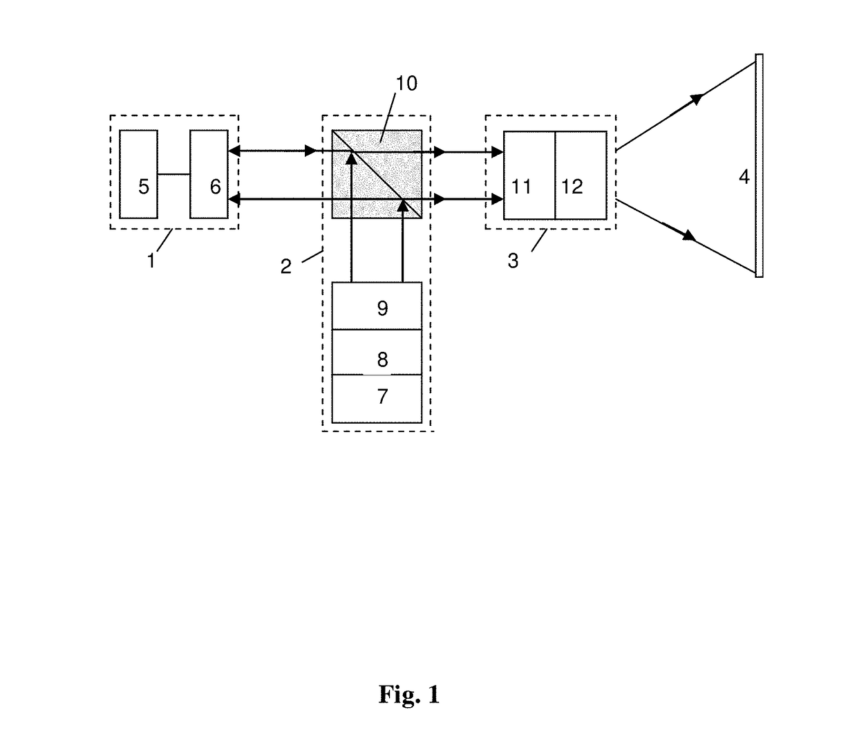
[0063]To implement the present invention, a few experimental samples of components of a video projector were made, namely, display cells with helix-free FLC for FLCoS-structure and FLC based a despeckler, which was inserted in the channel of data readout with laser diode. The scheme of scanning the readout and deployed images on a projection screen was also simulated, and the characteristics of indicated components and units for readout and scanning were measured.

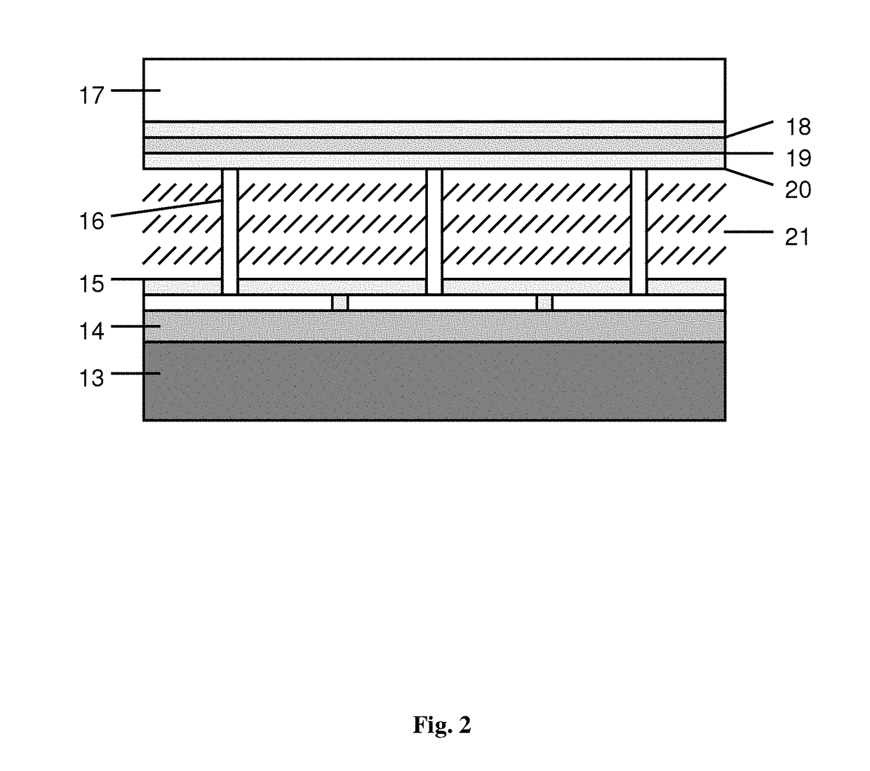
[0064]For FLCoS-structure FLC with compensated helix was used, where a helix with a pitch of 0.45 micrometers was suppressed due to the interaction of chiral additives with opposite signs of the optical activity. Such FLC possessed the following material parameters: coefficient of rotational viscosity γφ=0.7 Poise, spontaneous polarization PS=40 nC / cm2, and the modulus of elasticity KΨ, determining the deformation along smectic layers, was 1·10−12 Newton. The temperature range of the existence of ferroelectric phase in used...


PUM

PropertyMeasurementUnit
frequencyaaaaaaaaaa
sizeaaaaaaaaaa
voltageaaaaaaaaaa

Abstract

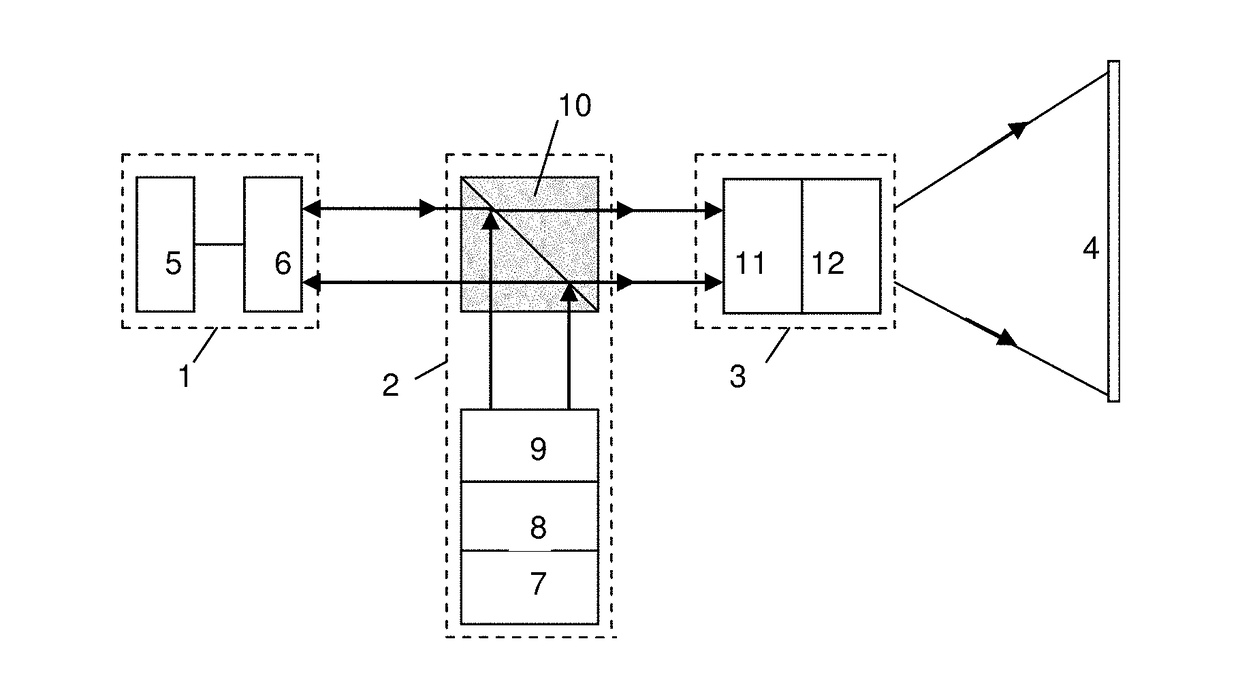
The invention relates to the field of optoelectronics, and may be used in devices and of visualization, displaying, storage and processing of information, in particular in projection displays, etc. Video projector consists of a liquid crystal micro display based on structure FLCoS, and an optical unit of reading the information formed in the structure FLCoS, containing a light source and projection optics, optically coupled to the structure FLCoS, and a screen, onto which the information is projected. As the electro-optical material the low-voltage ferroelectric liquid crystal (FLC) with compensated helix providing physically realizable, continuous, halftone, hysteresis-free modulation characteristic is used in the structure FLCoS. Lasers of red, green and blue radiation serve as the sources of light in three different color channels RGB. To destroy the ability of their radiation to the interference, a cell with FLC is inserted into the optical unit of information reading that implements fast electrically controlled spatial phase light modulation with a depth of ≧π, and in order to form on the screen the information blocks with a capacity of 108 . . . 109 pixels, with different geometric configurations a two-dimensional scanner is input, which optically coupled to the optical unit of information reading and to the screen. The technical result is an increase of frame rate, expanding the color gamut, brightness enhancement, noise reduction.

Description

CROSS-REFERENCE TO RELATED APPLICATION[0001]This application is a 371 national stage application of International Application PCT / RU2013 / 000439, filed May 29, 2013, and claims the priority of Russian Application No. 2012122120, filed on May 30, 2012.FIELD OF TECHNOLOGY[0002]The invention relates to the field of optoelectronics, and may be used in devices and systems of visualization, displaying, storage and processing the information with high information capacity, particularly in two-dimensional and three-dimensional projection displays, in devices and systems of optical advertisements and show-business, etc.BACKGROUND OF THE INVENTION[0003]Displays as devices of information displaying are one of the key elements of information and communication systems, including television systems. The increase of bandwidth, or informational capacity of such systems is an actual task. Its solution is provided both by increasing the number of parallel channels (relative to displays—the number of e...

Claims


Application Information

Patent Timeline
Patent Type & Authority Patents(United States)
IPC IPC(8): G03B21/00G02F1/141G02B27/48H04N9/31G03B21/20
CPCG03B21/006G02B27/48G02F1/141G03B21/208G03B21/2033H04N9/3129H04N9/3141G02F1/1416G02F2001/1414G02F1/1414
Inventor KOMPANETS, IGOR NIKOLAEVICHANDREEV, ALEKSANDR LVOVICH
Owner KOMPANETS IGOR NIKOLAEVICH
Learn More