

RAID failure prevention
a technology of data storage and failure prevention, applied in the field of data storage, can solve the problems of raid failure, raid failure, and raid failure, and achieve the effects of reducing the occurrence of data unavailability and data loss, and improving the control of replacements in tim
- Summary
- Abstract
- Description
- Claims
- Application Information
AI Technical Summary
Benefits of technology
Problems solved by technology
Method used
Image

Examples
Embodiment Construction
[0018]Various aspects of the invention may be implemented partially or completely in software using computer program code. The computer program code is stored on non-transitory computer-readable memory and utilized by processing hardware to implement instructions corresponding to certain steps. The program code may be provided as a computer program product or be integrated into network storage equipment. All of the illustrated devices may include processing hardware and non-transitory storage media capable of storing and implementing computer program code.
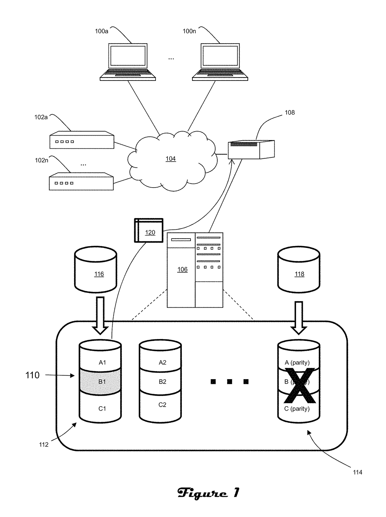
[0019]FIG. 1 illustrates a simplified network environment in which applications running on devices such as user terminals 100a through 100n (including but not limited to personal computing devices of any kind) and servers 102a through 102n (including but not limited to computing devices of any kind which perform tasks for other devices) utilize data maintained by data storage resources of a data storage subsystem via network 104. T...
PUM
 Abstract
Description
Claims
Application Information