Supercharge Your Innovation With Domain-Expert AI Agents!

Submerged oil storage, loading and offloading system

a technology of oil storage and floating structure, applied in the direction of artificial islands, transportation and packaging, packaging, etc., can solve the problems of affecting the safety of workers, the location of temporary oil storage system is important, and the cost of floating structure is usually much higher than a conventional fixed platform. , to achieve the optimal fluidity of stored oil, the effect of good thermal insulation and excessive buoyancy

Inactive Publication Date: 2017-10-10
LEE WILLIAM WEI
View PDF21 Cites 1 Cited by
  • Summary
  • Abstract
  • Description
  • Claims
  • Application Information

AI Technical Summary

Benefits of technology

The patent describes a new oil storage system that solves the problems of traditional dry and wet storage methods. It is submerged and achieves better insulation, can store water-soluble liquids, and is balanced with water depth, eliminating the need for a separate water tank. The system is designed to maximize oil storage capacity and eliminate the need for paired pumps. Its flexible containers are expanded and contracted during loading and offloading operations, allowing for efficient oil transfer. The oil storage system has applications in shallow water marginal oil field development and deepwater floating platforms.

Problems solved by technology

The location of a temporary oil storage system is an important issue.
However, placing oil compartments beneath the process modules and living quarters could constitute a serious safety hazards.
An even more critical issue is that this arrangement places a large mass at the platform top with a large weight variation during a loading and offloading operation, which could greatly influence the dynamic characteristics of the platform.
Therefore, this option has been only used for very shallow water fixed platform applications so far in the offshore industry.
However, the cost of a floating structure is usually much higher than a conventional fixed platform because the floating structure is subject to a large wind and wave induced environmental loading and it requires an expensive station keeping system to keep the floating structure in location.
Therefore, floating structures are usually applied in deep water applications or some shallow water applications where a subsea pipeline system becomes too expensive to be feasible.
However, a subsea oil storage system usually faces many challenges under different types of applications.
One of the most critical challenges is how to handle a large amount of buoyancy and related weight variations during the system's loading and offloading operations.
However, the wet storage method also possesses three major disadvantages.
The first disadvantage is the environmental pollution concern.
Under the dynamic motions, the contact surface between oil and seawater could produce a mixed layer to cause environmental pollution if discharged out to the sea.
The second disadvantage of the wet storage method is the issue of thermal insulation.
It is very hard to keep oil warm with the existence of a large contact surface between warm oil and cold seawater.
The third disadvantage is that it cannot store water-soluble liquids such as methanol.
Because of these critical disadvantages, especially with the environmental pollution concerns, this wet storage method has had very few field applications so far, either for fixed platforms or for floating platforms, in spite of the tremendous efforts made in the offshore industry.
However, this simple dry storage method faces two critical challenges during its service life.
The first challenge is the large buoyancy issue due to the emptied room of the tank during an oil offloading process.
The second challenge is the inert gas induced environmental pollution concern.
However, the required inert gas operations such as generating, blanketing and venting could become another source of pollution hazards.
Due to the above concerns, so far there have been only a very limited number of field applications, mostly in the form of concrete gravity based platforms, in the offshore oil & gas industry.
However, this system gives rise to three concerns.
Firstly, the oil storage volume utilization is low.
More than 50% of the total system volume cannot be utilized for oil storage, but has to be left for containing seawater and inert gas.
Secondly, both liquid storage compartment and water compartment have to be designed as pressured vessels because of the existence of inert gas.
Thirdly, the system operation is heavily dependent on a complex system using a pair of coupled pumps for oil and for water separately.
This arrangement could become a safety concern during the oil storage system operation.

Method used


Image

  • Submerged oil storage, loading and offloading system
  • Submerged oil storage, loading and offloading system
  • Submerged oil storage, loading and offloading system

Examples


Embodiment Construction

[0041]Before explaining the disclosure in detail, it is to be understood that the system and method is not limited to the particular embodiments and that it can be practiced or carried out in various ways. It is also to be understood that the submerged oil storage tank system and method disclosed herein may be used in any body of water. The term “oil” may comprise crude oil and other hydrocarbon liquids. The term “water” may refer to seawater or fresh water.

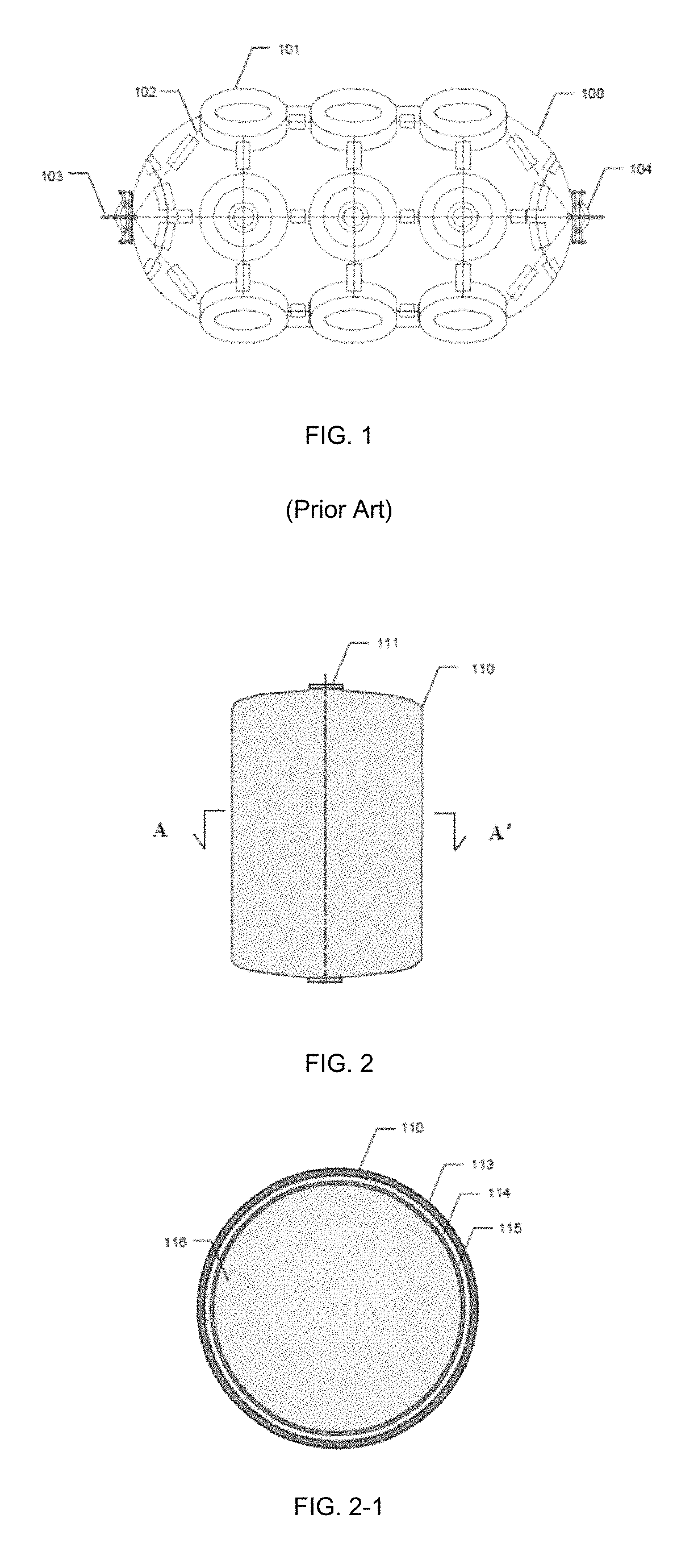
[0042]FIG. 1 illustrates a side view of a conventional floating pneumatic fender 100 in a horizontal position. Floating fenders 100 are commonly used to absorb dynamic impact forces between a jetty and a vessel side, and, in naval applications, between two vessel sides. A conventional floating pneumatic fender 100 is usually composed of three layers:

[0043](1) The outer layer consists of used tires 101, chains 102, a valve 103 and two towing rings 104 with one such ring at each end. The purpose of this layer is to protect the laye...


PUM


Abstract

An oil storage, loading and offloading system includes a submerged oil storage tank with multiple vertically placed flexible containers. The system directly connects to the topsides of an offshore oil production platform above water to assist oil loading and offloading operations. During loading, oil is pumped in and stored inside flexible containers, which are expanded to displace equivalent amount of water out of the oil storage tank; during offloading, oil is pumped out from flexible containers and the reduced volume of each contracted container is then filled in by the equivalent amount of water from the surroundings There is no physical contact between water and oil. The submerged tank on-bottom weight has a limited variation during the loading and offloading operations. This disclosed system can be utilized for fixed offshore platforms, especially for shallow water marginal field developments, and for deepwater floating platforms such as SPAR and semi-submersible (SEMI) structures.

Description

FIELD OF THE INVENTION[0001]The disclosure relates generally to a liquid storage, loading and offloading system using flexible containers and its associated applications for both fixed offshore oil production platforms and floating oil production platforms.BACKGROUND OF THE INVENTION[0002]After crude oil is produced from an offshore oil production platform in an oil field, there are two options to deal with the produced oil: 1) export the oil out through a subsea pipeline system; or 2) store the oil in a temporary storage facility, which could be a fixed part of the platform itself or a separate storage facility, and then transport the oil out via an oil shuttle tanker. If the production of the field in terms of quantity or duration is insufficient to justify the cost of a subsea pipeline connecting the platform to the shore, a platform with a safe, reliable and low cost temporary oil storage system must be provided for the development of such a field.[0003]The location of a tempora...

Claims


Application Information

Patent Timeline
Patent Type & Authority Patents(United States)
IPC IPC(8): E21B7/136E02B17/00B65D88/16E02B17/02E21B15/02B65D88/22B65D88/74B65D88/78B65D88/54B65D90/04B65D90/12
CPCE02B17/02B65D88/16B65D88/22B65D88/54B65D88/74B65D90/046B65D90/12E02B17/003E21B7/136E21B15/02B65D88/78E02B2017/0056E02B2017/0078
Inventor LEE, WILLIAM WEI
Owner LEE WILLIAM WEI
Features
  • R&D
  • Intellectual Property
  • Life Sciences
  • Materials
  • Tech Scout
  • Unparalleled Data Quality
  • Higher Quality Content
  • 60% Fewer Hallucinations
Learn More