Check patentability & draft patents in minutes with Patsnap Eureka AI!

Device for laser cutting within transparent materials

a laser cutting and transparent material technology, applied in laser beam welding apparatus, welding/soldering/cutting articles, manufacturing tools, etc., can solve the problems of increasing the extent of possible side effects caused by the mechanical effect of laser-produced shock waves and cavitation bubbles, and the total energy dose of energy is reduced, so as to avoid photochemical and photomechanical side effects. , the effect of avoiding the total energy dos

Active Publication Date: 2017-10-24
UNIV ZU LUBECK
View PDF16 Cites 0 Cited by
  • Summary
  • Abstract
  • Description
  • Claims
  • Application Information

AI Technical Summary

Benefits of technology

The invention is a laser cutting device for transparent materials that improves the precision of laser cuts with significantly fewer spots or a lower total dose of energy than required in previous technologies. It achieves this using vortex beams that produce a larger focal diameter with the same focal length, allowing for larger spot intervals and faster cutting speed, while avoiding adverse mechanical side effects or exceeding a tolerable dose of radiation. The invention also features a mode conversion system that facilitates cutting perpendicular to the beam incidence direction and increases the cutting speed by requiring fewer grid points. Additionally, it has applications in lens fragmentation and refractive eye surgery.

Problems solved by technology

Energy inputs due to residual transmissions into the retina are considered virtually impossible.
Especially for living tissue is produced a dose problem, because the extent of possible UV-induced photochemical side effects is scaled according to the reciprocity law of Bunsen and Roscoe with the total irradiation dose (J / cm2).
If the grid point spacing, however, is made too large, the single pulse energy must be increased so much that the cutting precision suffers and the extent of possible side effects caused by the mechanical effect of laser-produced shock waves and cavitation bubbles increases significantly.
However, the aforementioned means for mode conversion of non-helical into helical laser light are either difficult to prepare, suitable only for limited laser power (e.g., phase plates made of plastic and diffraction grating designed as a structured metallization or as a matrix of liquid crystals) or make demands on the non-helical light, which are not met by conventional laser sources for materials processing (e.g. the occurrence of certain higher Gaussian modes).
However, such components with a continuous phase shift can not yet be produced from a material since it would need to withstand the very high laser power.

Method used


Image

  • Device for laser cutting within transparent materials
  • Device for laser cutting within transparent materials
  • Device for laser cutting within transparent materials

Examples


Embodiment Construction

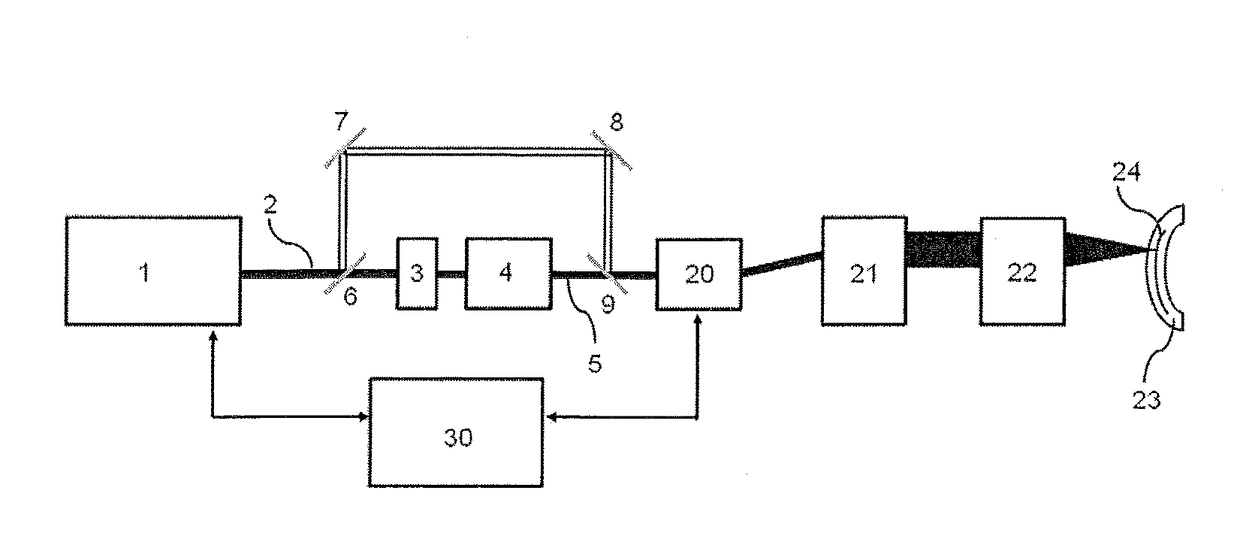
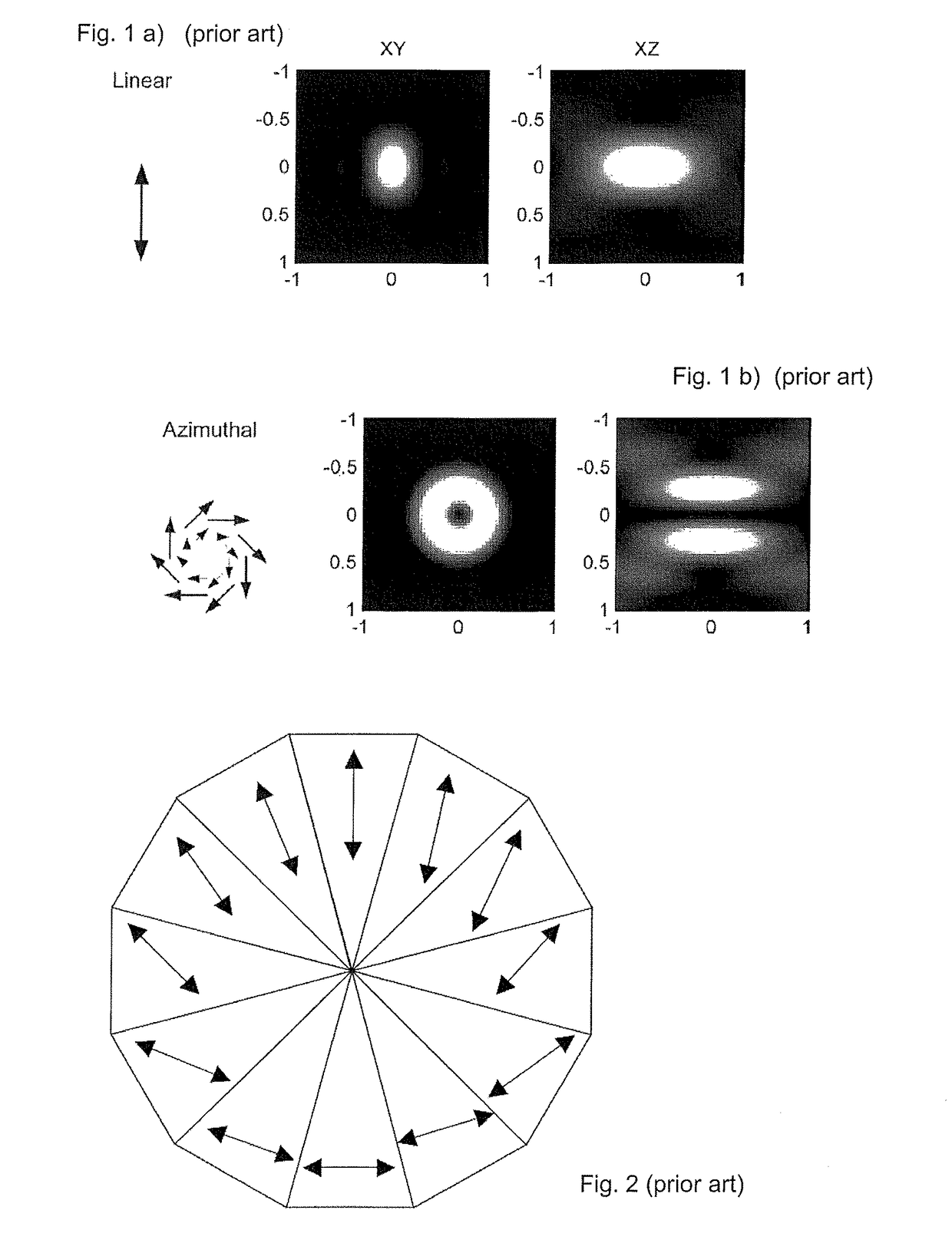
[0057]As explained above, the introduction of means for mode conversion to a linearly polarized laser beam with, for example Gaussian beam profile, creates a vortex beam (here: with azimuthal polarization). If this is focused into a transparent material, then a toroidal focal volume results as shown in FIG. 1 bottom. The direction of irradiation, is here along the z-axis. For comparison, the focus of the laser without the optical element placed in the beam shown in FIG. 1 top (all figures taken from Hao et al (2010)). The two right-side images show the xz-plane and thus the focal length along the z-direction, which in the Gaussian beam and vortex only slightly differ. From the two left images, however, it is plain to see that in the xy-plane perpendicular to the beam direction the focal diameter of the vortex beam is more than doubled. The singularity at the center of the vortex beam is usually of no relevance for the cutting action. The material is there also either decomposed or a...


PUM

PropertyMeasurementUnit
wavelengthaaaaaaaaaa
focal diameteraaaaaaaaaa

Abstract

A laser cutting device for transparent material (23), which device is designed to focus the laser light (2) into a plurality of predetermined spots within the material (23), wherein the spots lie on a predetermined cutting line or cutting area (24) running substantially perpendicularly to the direction of incidence of the laser light (2), wherein the device comprises means for mode conversion (3) into laser light having a helical phase front (5), which means can be brought into and out of the beam path of the laser light (2).

Description

BACKGROUND OF THE INVENTIONField of the Invention[0001]The invention relates to a laser cutting device for a transparent material which is adapted to focus the laser light (laser radiation) into a plurality of predetermined spots in the material, wherein the spots are located on a predetermined cutting line or cutting area, which is substantially perpendicular to the direction of irradiation of the laser light. The invention also relates to a device for laser processing of biological tissue, particularly of the living eye.Description of the Related Art[0002]The production of fine effects in laser material processing requires the localized deposition of low quantities of energy. In materials transparent to laser light, such as glass, quartz water, non-pigmented body tissues or cells, a localized energy deposition can be carried out by multi-photon processes in the form of multiphoton ionization and avalanche ionization, which lead to the formation of plasma (quasi-free charge carrier...

Claims


Application Information

Patent Timeline
Patent Type & Authority Patents(United States)
IPC IPC(8): A61F9/008B23K26/38B23K26/064B23K103/00
CPCA61F9/0084A61F9/00827A61F9/00836B23K26/064B23K26/38B23K2203/50A61F2009/00853A61F2009/00872A61F2009/00887A61F2009/00897B23K2203/32A61F2009/0087B23K2103/32B23K2103/50
Inventor VOGEL, ALFREDLINZ, NORBERTFREIDANK, SEBASTIAN
Owner UNIV ZU LUBECK
Features
  • R&D
  • Intellectual Property
  • Life Sciences
  • Materials
  • Tech Scout
  • Unparalleled Data Quality
  • Higher Quality Content
  • 60% Fewer Hallucinations
Learn More