Method of making rotary cutting dies

a cutting die and rotary technology, applied in the field of rotary cutting dies, can solve the problems of difficult manufacture and resharpening, and achieve the effects of accurate positioning of workpieces, reducing cutting force, and prolonging useful life in servi

a cutting die and rotary technology, applied in the field of rotary cutting dies, can solve the problems of difficult manufacture and resharpening, and achieve the effects of accurate positioning of workpieces, reducing cutting force, and prolonging useful life in servi

USRE37366E1Inactive Publication Date: 2001-09-18BERNAL

Image

  • Method of making rotary cutting dies
  • Method of making rotary cutting dies
  • Method of making rotary cutting dies

Examples


Embodiment Construction

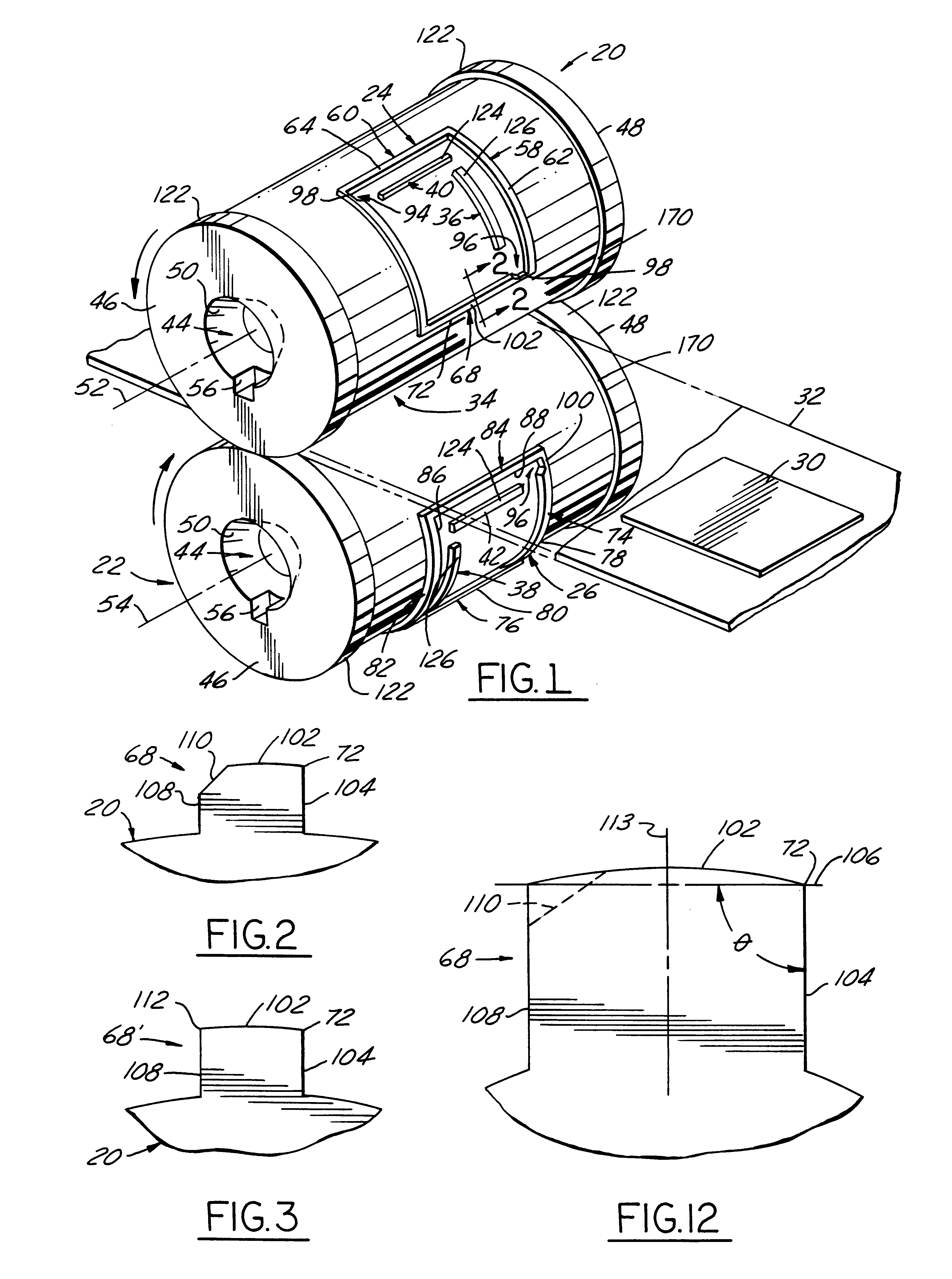
Referring in more detail to the drawings, FIG. 1 illustrates a pair of cutting die cylinders 20 and 22 embodying this invention with coacting cutting blades 24 and 26 thereon which when the cylinders are co-rotating cut generally rectangular blanks 30 from a web 32 of thin material, such as paper board, passing through the nip 34 of the die cylinders. Preferably, removal of blanks from the die cylinders is facilitated by pairs of ejector lands 36, 38 and 40, 42 within the perimeter of the cutting blades.

In use, each die cylinder is journalled for rotation by a pair of arbor assemblies having coaxial spindles with opposed noses (not shown), received in complementary recesses 44 in the opposed ends 46 and 48 of each die cylinder. Each recess is a bore with a frusto conical sidewall 50 tapered inwardly from its associated cylinder end which provides a locator surface engagable with a complementary tapered surface on the nose of an associated spindle. For each die cylinder, the frusto c...


PUM

PropertyMeasurementUnit
temperatureaaaaaaaaaa

Abstract

A method of making a pair of rotary die cylinders with lands having coacting cutting edges which cut blanks from a web of material passing through the nip of the rotating dies. In cross section each land has an outer face and a pair of spaced apart side faces which are parallel to each other and perpendicular to the chord of the outer face to provide a clean cut and facilitate release of the cut blank from the cutting blades as it emerges from the nip of the dies. The die cylinders are journalled for rotation by recesses with frusto conical locating surfaces in their opposed ends. Each die cylinder is made by machining the recesses in the opposed ends of a generally cylindrical workpiece of tool steel and then utilizing the recesses to locate and orient the workpiece relative to a cutting tool to produce a cylindrical surface on the workpiece concentric with the axis of the recesses and then to machine away portions of the periphery of the cylindrical surface to form the cutting blade lands thereon. After machining is completed the cutting blade lands may be hardened by heat treating utilizing a laser beam directed onto the lands to heat them at an elevated temperature so that upon quenching they are hardened without any substantial hardening and resulting distortion of the core or body of the workpiece.

Description

FIELD OF THE INVENTIONThis invention relates to rotary die cutting of blanks from thin sheets or webs of material, and more particularly to improved rotary cutting dies and a method of making them.BACKGROUND OF THE INVENTIONFor many years, a pair of superimposed rotary dies with cutting blades on one of both cylinders have been used to cut blanks from a thin web of material passing through the nip of the dies. Typically, the thin web is of a material such as paper, paper board, cardboard, plastic film, metal foil, thin sheet metal and the like.U.S. Pat. No. 4,608,895 discloses a pair of rotary die cylinders with integral complementary cutting blades thereon which coact to sever a web of material passing through their nip. Each severing blade has an elongate land projecting generally radially outwardly from its cylinder and having in cross section an outer face and spaced apart depending side faces inclined towards each other at an acute included angle, and each inclined to its assoc...

Claims


Application Information

Patent Timeline
18 Sep 2001
Publication
USRE37366E1
IPC
B23D35/00; B26D7/26; B21B31/18; B21B27/03; B21B31/16; B21B31/12; B21B31/00
CPC
B21B27/03; B21B31/12; B21B31/18; B21B2203/02; B21B2203/34; B21B2203/36; B23D35/008; B26D7/2614
Inventors
COX, WILLIAM ALLEN; PFAFF, ALAN RAE