Extracorporeal circuit for peripheral vein fluid removal

a technology of peripheral veins and extracorporeal circuits, which is applied in the direction of suction devices, catheters, other medical devices, etc., can solve the problems of increased blood vessel constriction, fluid retention, abnormal hormone secretion, etc., and achieve the effect of removing the effect of the time course of input conductivity/concentration

Inactive Publication Date: 2005-11-08
GAMBRO LUNDIA AB
View PDF21 Cites 37 Cited by
  • Summary
  • Abstract
  • Description
  • Claims
  • Application Information

AI Technical Summary

Benefits of technology

[0019]FIG. 7 is a graph derived from the graph of FIG. 6 by eliminating the effect of the time course of the input conductivity / concentration function. The input fraction is a step function at zero normalized volume. The test object characterized by this figure is the extracorporeal circuit described by this invention.

Problems solved by technology

If blood flow decreases sufficiently, kidney function becomes impaired and results in fluid retention, abnormal hormone secretion and increased constriction of blood vessels.
The fluid overload and associated clinical symptoms resulting from these physiologic changes are the predominant cause for excessive hospital admissions, terrible quality of life and overwhelming costs to the health care system due to CHF.
This method is especially useful if CHF is in its final stage and drug treatment is no longer efficient.
Although attempts have been made to construct a streamlined flow path, the blood flow passage in the PRISMA™ system still had dead zones where fluid or blood stagnates and resides for a prolonged time while blood is otherwise flowing through the system.
If a fluid path contains poorly perfused dead zones where blood stagnates for a longer period, then blood clots will form at these sites and the clots eventually will block the entire circuit.
Other causes for the enhanced formation of blood clots are blood-air interfaces and obstructions in the fluid path, e.g., the commonly used “clot” filters in drip chambers.
This use of anticoagulants increases the risk of bleeding by the patient during and after treatment.
The insertion and use of central venous catheters are related to several risks that may result in death or severe impairment.
In particular, stenosis of the central vessels after use of catheters, which has been well documented, makes frequent insertion of central venous catheters impossible.
The collapse of a vein would cause the blood circuit to issue frequent alarms that would require continuous observation by trained personnel.

Method used


Image

  • Extracorporeal circuit for peripheral vein fluid removal
  • Extracorporeal circuit for peripheral vein fluid removal
  • Extracorporeal circuit for peripheral vein fluid removal

Examples


Embodiment Construction

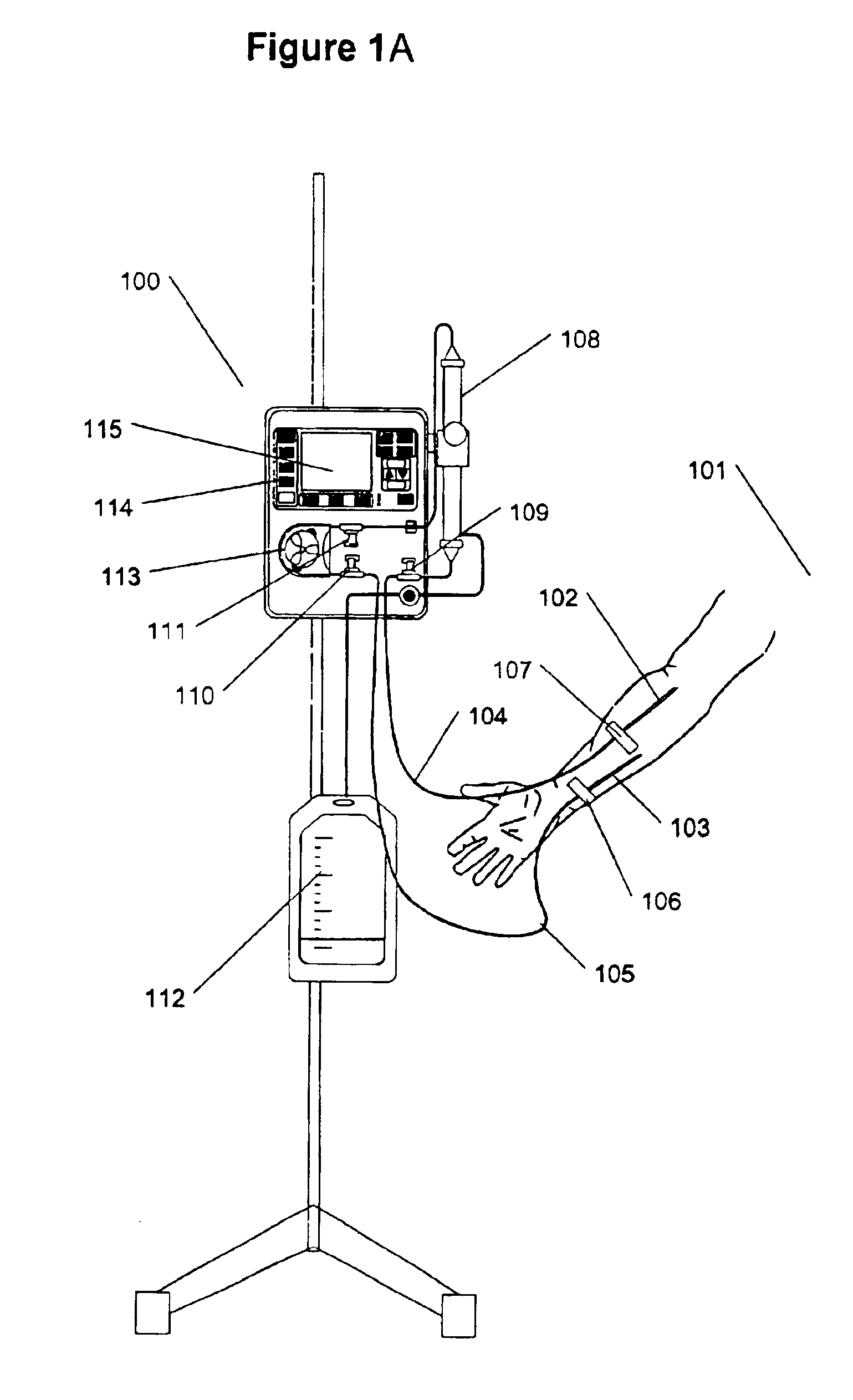
[0021]FIG. 1A illustrates the treatment of a fluid overloaded patient with a blood treatment system 100. Patient 101 can undergo treatment while in bed or sitting in a chair. Patient can be conscious or asleep. To initiate treatment two relatively standard 18G needles 102 and 103 are introduced into suitable peripheral veins (on the same or different arms) for the withdrawal and return of the blood. This procedure is no different from blood draw or IV therapy. Needles and attached to tubing 104 and 105 and secured to skin with attachments 106 and 107. The blood circuit that consists of the blood filter 108, tubes, pressure sensors 109, 110 and 111 and the ultrafiltrate collection bag 112. The circuit is supplied in one sterile package and is never reused. It is easy to mount on the pump 113 and can be primed and prepared ready for operation within minutes by one person.

[0022]During operation, the present invention requires minimal intervention from user. User sets the maximum rate a...


PUM


Abstract

An extracorporeal blood circuit is disclosed for withdrawing, filtering and returning blood from peripheral blood vessels. The blood passage in the circuit extends through a withdrawal tube connected to a catheter in a peripheral vein, a filter, one or more pressure sensors and return tube also connected to a catheter in a peripheral vein (which may or may not be the same vein as used for the withdrawal tube). The blood passage is air free, and has smooth passage walls which promoted continuous and uniform flow of the blood through the circuit.

Description

[0001]This application is a continuation-in-part (CIP) application of U.S. patent application Ser. No. 09 / 618,759, filed Jul. 18, 2000, which is based on Provisional Application 60 / 206,232, filed May 23, 2000, and a CIP application of U.S. patent application Ser. No. 09 / 660,195, filed Sep. 12, 2000. These applications are commonly-owned and incorporated by reference in their entirety.FIELD OF INVENTION[0002]This invention relates to methods and apparatus for treatment of congestive heart failure (CHF) by removal of excessive fluids, such as water. In particular, the invention relates to an extracorporeal circuit with minimized blood residence time.BACKGROUND OF THE INVENTION[0003]Congestive Heart Failure (CHF) is the only form of heart disease still increasing in frequency. According to the American Heart Association, CHF is the “Disease of the Next Millennium”. CHF is a condition that occurs when the heart becomes damaged and reduces blood flow to the organs of the body. If blood f...

Claims


Application Information

Patent Timeline
Patent Type & Authority Patents(United States)
IPC IPC(8): A61M1/34A61M1/36A61M25/16
CPCA61M1/34A61M1/3639A61M1/3663A61M2205/12A61M2205/3393A61M1/361A61M1/3612A61M2205/3331A61M2205/3334A61M1/341A61M1/3653A61M1/362265A61M1/362264A61M1/36224A61M1/36225
Inventor POLASCHEGG, HANS-DIETRICHBERNARD, STEVENLEVIN, HOWARD R.GELFAND, MARK
Owner GAMBRO LUNDIA AB
Why Eureka
Try Eureka