Electromechanical drive for track-laying vehicles

a technology of electric motors and tracklaying vehicles, applied in electric propulsion mounting, transportation and packaging, gearing, etc., can solve the problems of limited arrangement of motors in vehicles, a lot of construction space for motors, etc., and achieve the effect of high integration and compactness

Inactive Publication Date: 2006-07-11
RENK AG
View PDF17 Cites 8 Cited by
  • Summary
  • Abstract
  • Description
  • Claims
  • Application Information

AI Technical Summary

Benefits of technology

[0006]An object of the present invention is to provide a more highly in

Problems solved by technology

These motors require a lot of construction space and

Method used


Image

  • Electromechanical drive for track-laying vehicles
  • Electromechanical drive for track-laying vehicles
  • Electromechanical drive for track-laying vehicles

Examples


Embodiment Construction

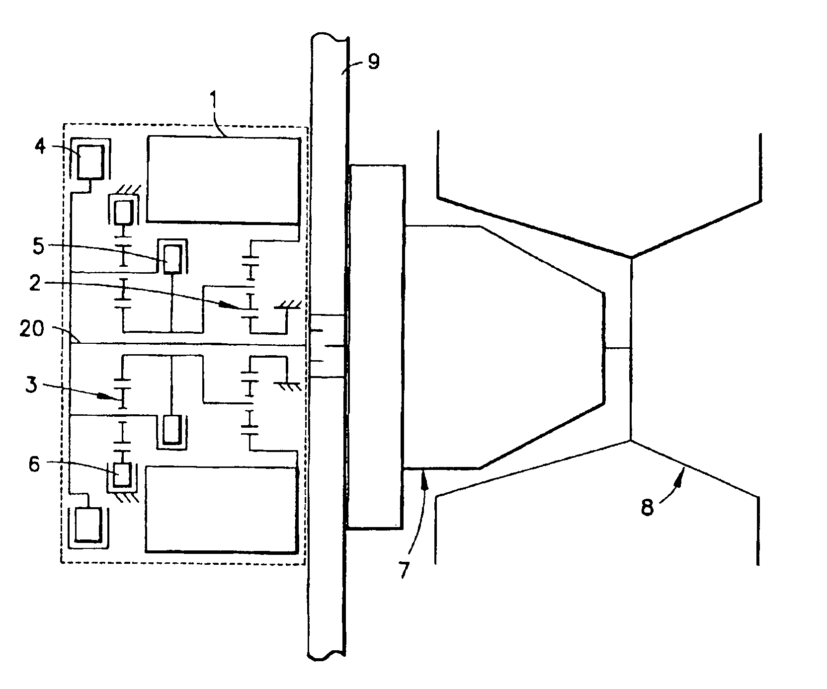
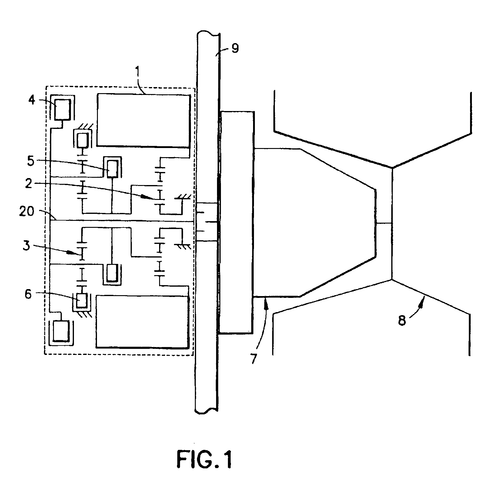
[0016]The basic construction of an exemplary embodiment of a drive according to the invention is shown in FIG. 1. An electric motor 1 drives the ring gear of an epicyclic gear unit 2, which is provided as a reducing fixed stage. The electric motor may be of a type operable to allow brief operation close to a motor cut-off output. The output of epicyclic gear unit 2 is effected via its revolving web, which, with clutch 5 closed and at the same time clutch 6 open, directly drives the output shaft 20 of the drive. By controlled and thus matched opening of the clutch 5 and closing of the clutch 6, the epicyclic gear unit 2 drives the sun gear of an epicyclic gear unit 3. Since this epicyclic gear unit 3, in this set-up, drives the output shaft 20 via its web. A further gear stage is thus connected in which the revolving planet gears are rotatably mounted. Accordingly, the epicyclic gear units 2, 3 and the clutches 5, 6 comprise a shiftable transmission.

[0017]The brake 4 is firmly connec...


PUM


Abstract

An electromechanical drive for track-laying vehicles in which the two drive sides have no mechanical coupling and permits smaller overall lengths and overall diameters. As a result, the flexibility of the arrangement of the drive components compared is further increased. The drive includes an electric traction motor, at least one variable-speed mechanical gear unit, and at least one brake. At least one of these components is arranged inside the rotor of the electric motor, and the remaining components are arranged laterally at the electric motor in such a way as to lie coaxially in approximately one plane.

Description

BACKGROUND OF THE INVENTION[0001]1. Field of the Invention[0002]The invention relates track laying vehicles, and more particularly to an electromechanical drive for track-laying vehicles.[0003]2. Description of the Related Art[0004]It is known that electric drives for track-laying vehicles, compared with conventional, fully automatic, hydromechanical power-shift transmissions, permit increased flexibility in the component arrangement as well as a more favorable energy management of the vehicle with infinitely variable traction drive. The high demands made on the traction motor and on the power electronics in purely electic drives—without mechanical shift stages—leads to electric motors of large diameters. These motors require a lot of construction space and can only be arranged in vehicles to a limited extent.[0005]Avoiding these disadvantages has led to the development of electromechanical drives. German Patent No. 37 28 171 C2 shows an electromechanical drive block which has an el...

Claims


Application Information

Patent Timeline
IPC IPC(8): F16H3/72B60K1/00F16H48/06
CPCB60K7/0007B60K17/046B60K2007/0038B60K2007/0092F16H3/66F16H2200/0034F16H2200/2007F16H2200/2038F16H2200/2097
Inventor NAUNHEIMER, HARALDHUF, ANTON
Owner RENK AG
Why Eureka
Try Eureka