
Method and equipment for reducing vehicle energy consumption

A vehicle and energy consumption technology, applied in control devices, vehicle components, transmission control, etc., can solve problems such as low output torque of internal combustion engines, low vehicle driving efficiency, and endangering crankshaft safety, achieving high power performance and economic performance. Improves practicality and prolongs life

Inactive Publication Date: 2008-11-05
罗显平
View PDF10 Cites 0 Cited by
  • Summary
  • Abstract
  • Description
  • Claims
  • Application Information

AI Technical Summary

Problems solved by technology

Therefore, the maximum output torque of the engine is not the maximum value when the piston thrust is maximum, so that the output torque of the internal combustion engine is very low
Moreover, when the piston obtains the maximum thrust at the top dead center, the thrust and the connecting rod act on the central axis of the crankshaft perpendicularly on the same straight line, the crankshaft reaction force is the largest, and the output torque is zero, so that the crankshaft is subjected to 3-5 MPa for gasoline engines and 5 MPa for diesel engines. The instantaneous impact force generated by ~10MPa air pressure, slight poor lubrication and sudden change resistance from the load will endanger the safety of the crankshaft
2. Since the integrated internal combustion engine needs to increase the crank radius or cylinder bore to increase the output torque, it will inevitably be limited by the need to increase the amount of fuel, the body volume, etc., so the current internal combustion engine crank radius is very short (that is, the stroke is short)
Because they all use integrated engines or electric motors or hybrid power to directly drive vehicles, they fail to efficiently utilize mechanical energy in the driving of vehicles, and do not recover useless work to participate in work and other factors, resulting in low driving efficiency and high energy consumption.

Method used


Image

  • Method and equipment for reducing vehicle energy consumption
  • Method and equipment for reducing vehicle energy consumption
  • Method and equipment for reducing vehicle energy consumption

Examples


Embodiment Construction

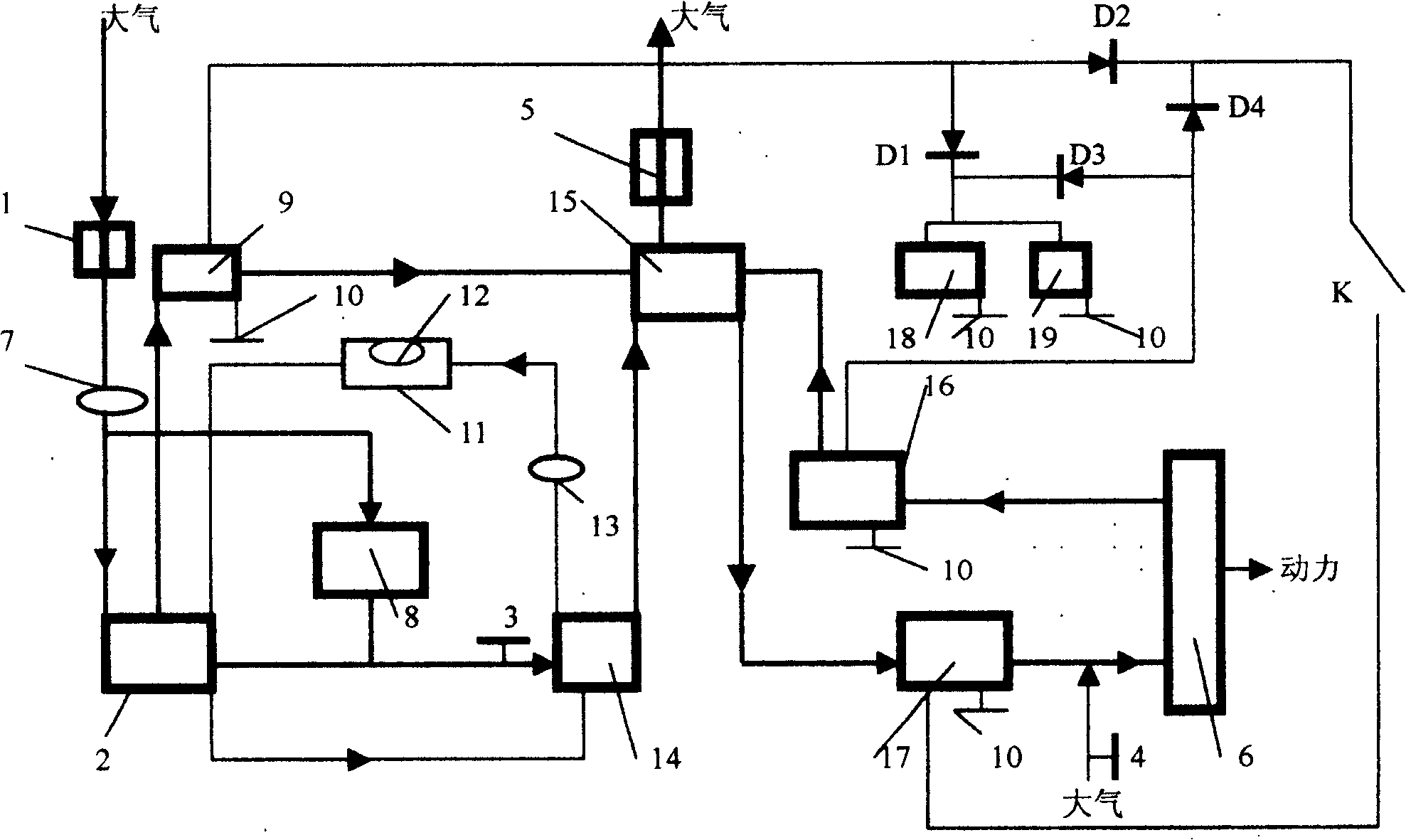
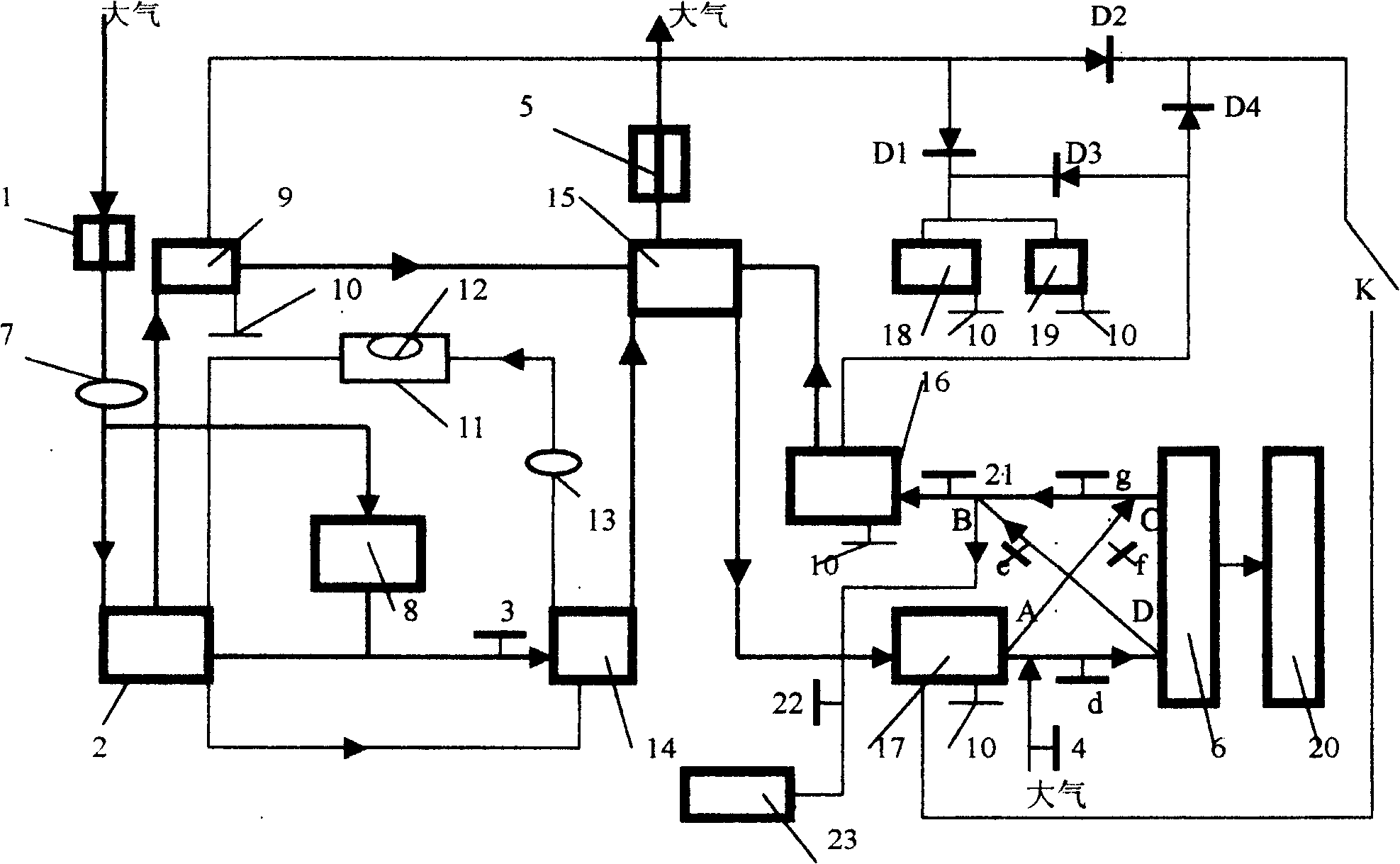
[0045] Because the embodiment when using electric air compressor and canned compressed air as prime mover is similar to the embodiment when using internal combustion engine type air compression as prime mover, below in conjunction with accompanying drawing, take internal combustion engine type air compressor 2 as prime mover as example The present invention is further described.

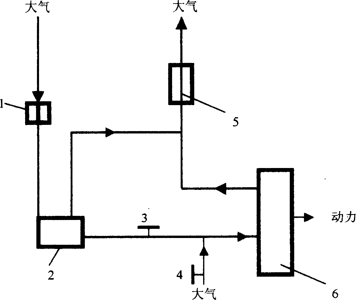
[0046] figure 1 , is a kind of original driven engine power plant, comprises by air compressor 2 and its air filter 1, valve (3,4), pipeline, muffler 5, two process engine 6, and air compressor passes its output air valve 3. The pipeline is connected to the intake manifold of a secondary process engine 6 that converts the internal energy of compressed air into mechanical energy. The exhaust gas of the internal combustion engine of the secondary process engine 6 and the air compressor enters the atmosphere through the muffler 5 and is set at the output gas valve 3 to The valve 4 between the cylinders...


PUM


Abstract

The invention discloses a method reducing energy consumption of vehicles and its device, relating to vehicle and engine. It connects an air compressor or bottled compressed air with branched inlet pipe of two-course engine converting inner energy of compressed air to mechanical energy, by gas output valve and pipeline of the air storage tank, there is a valve set between the air output valve and an cylinder of the two-course engine, where the valve can lead atmosphere to the cylinder, which composes a power device for original driven engine, the power output end of the two-course engine is connected with the driving device of driving wheels of vehicle, the driver operates and controls the air output valve to release air and control the output power of the two -course engine to drive vehicle. It can use reactive power or external energy to take part in doing work at the same time. It enhances running efficiency to 70%, even higher. It makes the energy consumption and pollution of vehicle and engine super low.

Description

technical field [0001] The present invention relates to a vehicle and an engine, more specifically, it relates to a method and a device for reducing energy consumption of the vehicle used to improve the energy utilization rate of the vehicle and the engine. technical background [0002] The energy consumption (also known as economic performance) of an internal combustion engine is generally defined and measured by the average fuel consumption rate g / kw.h (how many grams of fuel consumption per kilowatt-hour); for vehicles using internal combustion engines, the energy consumption of the vehicle is generally It is defined and measured by the average L / 100km or kg / 100km (how many liters or how many kilograms of fuel consumption per 100 kilometers); how many kilowatt-hours 100 kilometers consume) to define and measure. The less fuel or electricity consumed per unit distance, the less energy consumption of the vehicle. The prerequisite for reducing the energy consumption of the...

Claims


Application Information

Patent Timeline
IPC IPC(8): F02B41/00F02B29/00F02B33/00F02B53/00B60K20/02F16H63/00F15B21/00
CPCY02T10/146Y02T10/17Y02T10/14Y02T10/12
Inventor 罗显平
Owner 罗显平
Learn More