Temperature observation circuit

A technology for monitoring circuits and circuits, applied in thermometers, electrical components, measuring devices, etc., can solve the problems that integrated circuits cannot be fully cooled, do not have temperature hysteresis characteristics, and increase production costs

Inactive Publication Date: 2009-06-03
CHINA AEROSPACE TIMES ELECTRONICS CORP NO 771 RES INST
View PDF6 Cites 1 Cited by
  • Summary
  • Abstract
  • Description
  • Claims
  • Application Information

AI Technical Summary

Problems solved by technology

In addition, the resistive element will occupy a large chip area
therefore, figure 1 The main disadvantages of the circuit are: the resistance element is used, which is incompatible with the digital CMOS semiconductor process, which increases the production cost; the number of devices required is large, and the chip area occupied is large; it does not have temperature hysteresis characteristics, that is, the output of the temperature monitoring circuit , the temperature at which the circuit temperature is too high to indicate that the circuit temperature is overturned is the same as the temperature at which the output is indicated to indicate that the circuit temperature has returned to the normal range. When the control circuit makes the circuit temperature fall back to T1, instead of falling back to T2, which is smaller than T1, the circuit output signal is reversed again, indicating that the temperature control circuit stops working. After that, the circuit temperature rises quickly again, and the temperature of the circuit is monitored at T1. The output is reversed again, and so repeatedly, causing the temperature control circuit to start frequently, and the integrated circuit itself cannot be fully cooled

Method used


Image

  • Temperature observation circuit
  • Temperature observation circuit
  • Temperature observation circuit

Examples


Embodiment Construction

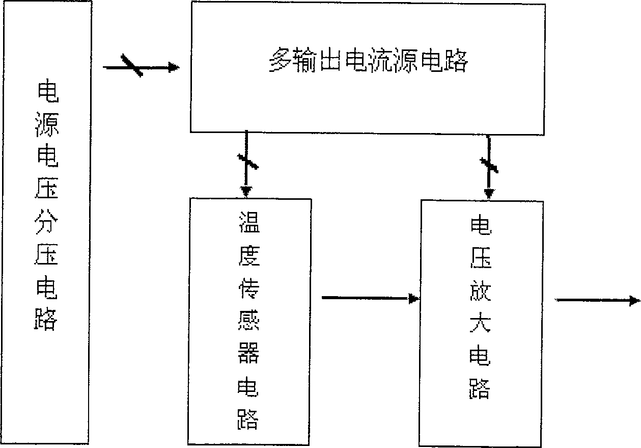
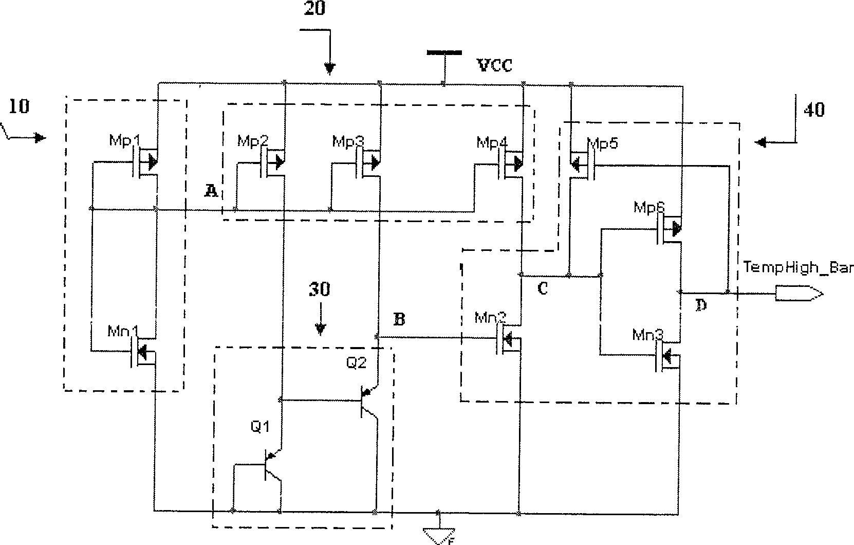
[0017] An implementation example circuit of the temperature monitoring circuit of the present invention is as image 3 As shown, it includes a power supply voltage divider circuit 10, a multi-output current source circuit 20, a temperature sensor circuit 30, and a voltage amplifying circuit 40 composed of a common source amplifier stage and an inverter amplifier stage.

[0018] The power supply voltage divider circuit 10 is: the source of the PMOS transistor Mp1 as an active resistor is connected to the power supply, the gate and the drain are short-circuited, and connected to point A, and the source of the NMOS transistor Mn1 as an active resistor Grounded, the gate and the drain are short-circuited, and also connected to point A, which is the output end of the power supply voltage divider circuit.

[0019] The multi-output current source circuit 20 includes PMOS transistors Mp2, Mp3, and Mp4 whose sources are connected to the power supply and whose gates are connected to the...


PUM


Abstract

The invention discloses a monitoring circuit capable of identifying whether the temperature of IC chip is higher than the temperature of safe operating area. The invention can monitor the variation of PN junction voltage, which is conducted by forward bias and flowing through a constant current, with temperature. The temperature monitoring circuit comprises a voltage bleeder circuit, a multi-output current source circuit, a temperature sensing circuit, and a voltage amplification circuit. The whole circuit does not use resistor unit. The gain of the voltage amplification circuit is controlled by forming positive feedback loop in the multiple amplification structures of the voltage amplification circuit, so that the circuit has dynamical characteristic of temperature hysteresis. Meanwhile, the positive feedback introduced into the voltage amplification circuit reduces the gain requirement to the voltage amplification circuit, and steepens the jump of the output signal of the circuit.

Description

technical field [0001] The invention relates to a semiconductor integrated circuit, in particular to a circuit for monitoring the temperature of the semiconductor integrated circuit. Background technique [0002] When the temperature of the integrated circuit is higher than the safe operating temperature, the circuit will not work normally, and even damage the devices in the integrated circuit due to overcurrent, so a temperature monitoring circuit is required to monitor the temperature of the circuit. According to needs, a high temperature threshold temperature T1 can be set, and when the circuit temperature reaches T1, the monitoring circuit will give an indication signal that the temperature is too high. According to the application, the indication signal can be used as a trigger signal of an alarm circuit, or used for frequency reduction of a clock signal, a shutdown control signal of a power device, and the like. [0003] At present, a temperature monitoring circuit kn...

Claims


Application Information

Patent Timeline
Patent Type & Authority Patents(China)
IPC IPC(8): G01K7/01H03K17/687
Inventor 汪西虎
Owner CHINA AEROSPACE TIMES ELECTRONICS CORP NO 771 RES INST
Why Eureka
Try Eureka