Insulated on-line monitoring system checker of high-voltage electric equipment
A technology for high-voltage electrical equipment and monitoring systems, applied in the field of calibration devices, can solve problems such as data errors, affecting user power supply, and inability to represent conditions, achieving the effects of simple inspection methods, ensuring inspection accuracy, and improving economic benefits and work efficiency
- Summary
- Abstract
- Description
- Claims
- Application Information
AI Technical Summary
Problems solved by technology
Method used
Image
Examples
Embodiment 1
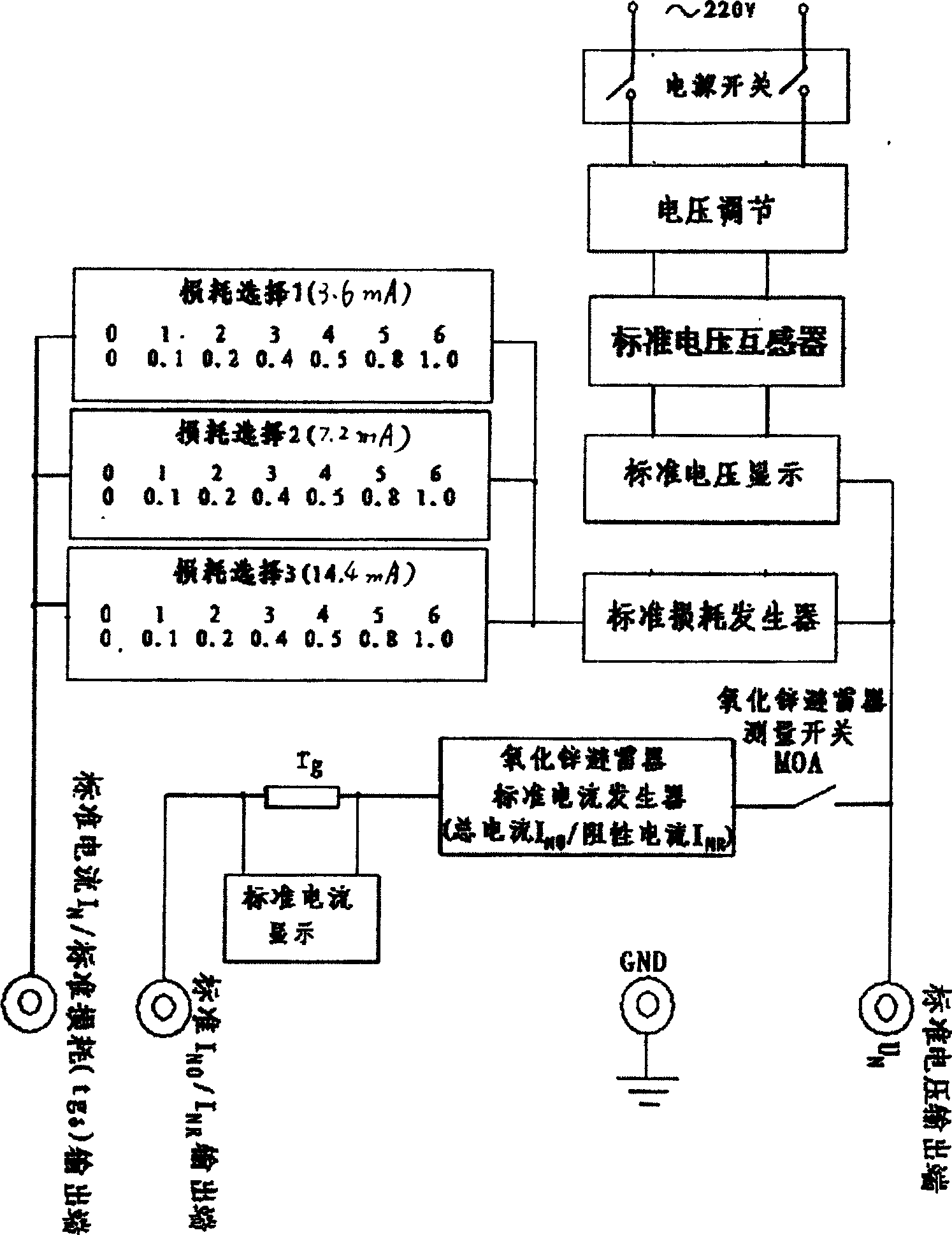
[0034] The calibrator of the insulation on-line monitoring system for high-voltage electrical equipment includes a power supply circuit, a standard dielectric loss and a standard current generator circuit, and a zinc oxide surge arrester total current and resistive current generator circuit, see figure 1 .
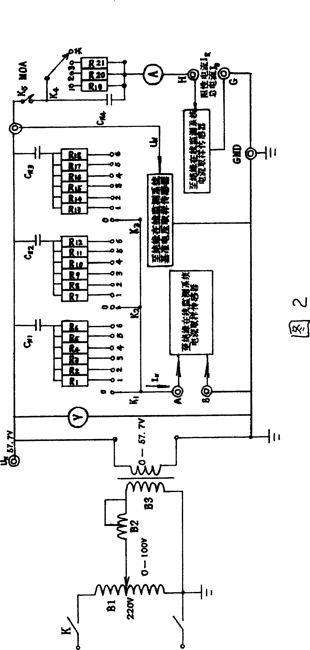
[0035] The power supply circuit includes contact-type auto-coupling voltage regulator B1, BCI type cantilever wire resistor B2 and standard voltage transformer B3. The input terminal of contact-type voltage regulator B1 is connected to 220V power supply, and the output terminal is connected to sliding wire resistance B2; The input terminal of the voltage transformer B3 is connected to the sliding wire resistance B2, and the output terminal is connected to the standard loss generator circuit; the output terminal is connected in parallel with a voltmeter, and the output terminal voltage is 57.7V;
[0036] Contact auto-coupling voltage regulator B1; model: TDGC-0.5; rated cap...
Embodiment 2
[0108] The capacities of the capacitors CN1, CN2, and CN3 in the standard dielectric loss and standard current generator circuits are 0.15μF; 0.38μF; 0.76μF;
[0109] The resistance values of resistors R1, R2, R3, R4, R5, R6, R7, R8, R9, R10, R11, R12, R13, R14, R15, R16, R17, and R18 are 12.7Ω; 25.4Ω; 50.8Ω; 63.5Ω; 101.6Ω; 127Ω; 7.58Ω; 15.16Ω; 30.32Ω; 37.9Ω; 60.64Ω; 75.8Ω; 3.79Ω; 7.58Ω;
[0110] The total current of the zinc oxide arrester and the capacitor C4 in the resistive current generator circuit are 0.5225; the resistance values of the resistors R19, R20, and R21 are 56.943kΩ; 113.886kΩ; 288.2115kΩ;
[0111] Others are with embodiment 1.
Embodiment 3
[0113] The capacities of the capacitors CN1, CN2, and CN3 in the standard dielectric loss and standard current generator circuits are 0.25μF; 0.42μF; 0.84μF; resistors R1, R2, R3, R4, R5, R6, R7, R8, R9, R10 , R11, R12, R13, R14, R15, R16, R17, R18 resistance are 21.2Ω; 42.4Ω; 84.9Ω; 106Ω; 169.6Ω; 212Ω; 8.38Ω; 16.76Ω; 33.52Ω; Ω; 83.8Ω; 4.19Ω; 8.38Ω; 16.76Ω; 20.95Ω; 33.52Ω; 41.9Ω;
[0114] The total current of the zinc oxide arrester and the capacitor C4 in the resistive current generator circuit are 0.5775μF;
[0115] The resistance values of resistors R19, R20, and R21 are 57.057kΩ; 114.114kΩ; 288.7885kΩ;
[0116] Others are with embodiment 1.
PUM
 Abstract
Description
Claims
Application Information
 - R&D
- Intellectual Property
- Life Sciences
- Materials
- Tech Scout
- Unparalleled Data Quality
- Higher Quality Content
- 60% Fewer Hallucinations
Browse by: Latest US Patents, China's latest patents, Technical Efficacy Thesaurus, Application Domain, Technology Topic, Popular Technical Reports.
© 2025 PatSnap. All rights reserved.Legal|Privacy policy|Modern Slavery Act Transparency Statement|Sitemap|About US| Contact US: help@patsnap.com


