Rotary type transducer main shaft device of supersonic vibrated drill

A spindle device and ultrasonic vibration technology, applied in the direction of fluid using vibration, etc., can solve the problems of difficulty in ensuring the rotation accuracy of the spindle and increase the complexity of the mechanism, and achieve the effect of simple structure, easy assembly and disassembly, and guaranteed rotation accuracy

Inactive Publication Date: 2009-12-09
BEIHANG UNIV
View PDF6 Cites 3 Cited by
  • Summary
  • Abstract
  • Description
  • Claims
  • Application Information

AI Technical Summary

Problems solved by technology

In the design of existing rotary ultrasonic processing equipment, in order to avoid the impact of vibration on peripheral equipment, most of them design the transducer and the rotary spindle as two parts, the spindle is hollow, and the transducer and the rotary spindle are connected by a thin flange. This increases the complexity of the mechanism to a large extent, making it difficult to guarantee the rotation accuracy of the spindle.

Method used


Image

  • Rotary type transducer main shaft device of supersonic vibrated drill
  • Rotary type transducer main shaft device of supersonic vibrated drill
  • Rotary type transducer main shaft device of supersonic vibrated drill

Examples


Embodiment Construction

[0024] The present invention will be further described in detail below in conjunction with the accompanying drawings.

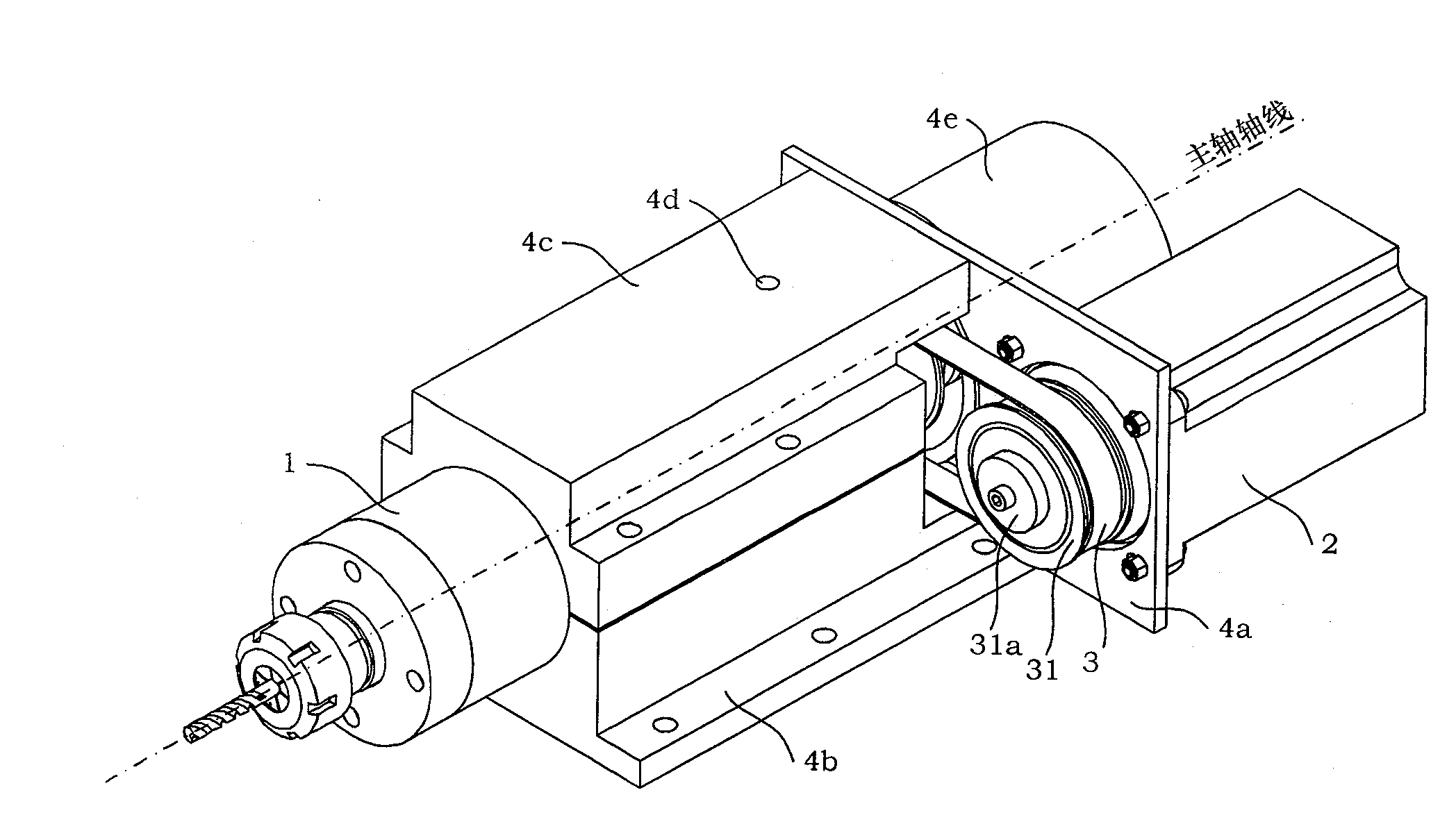
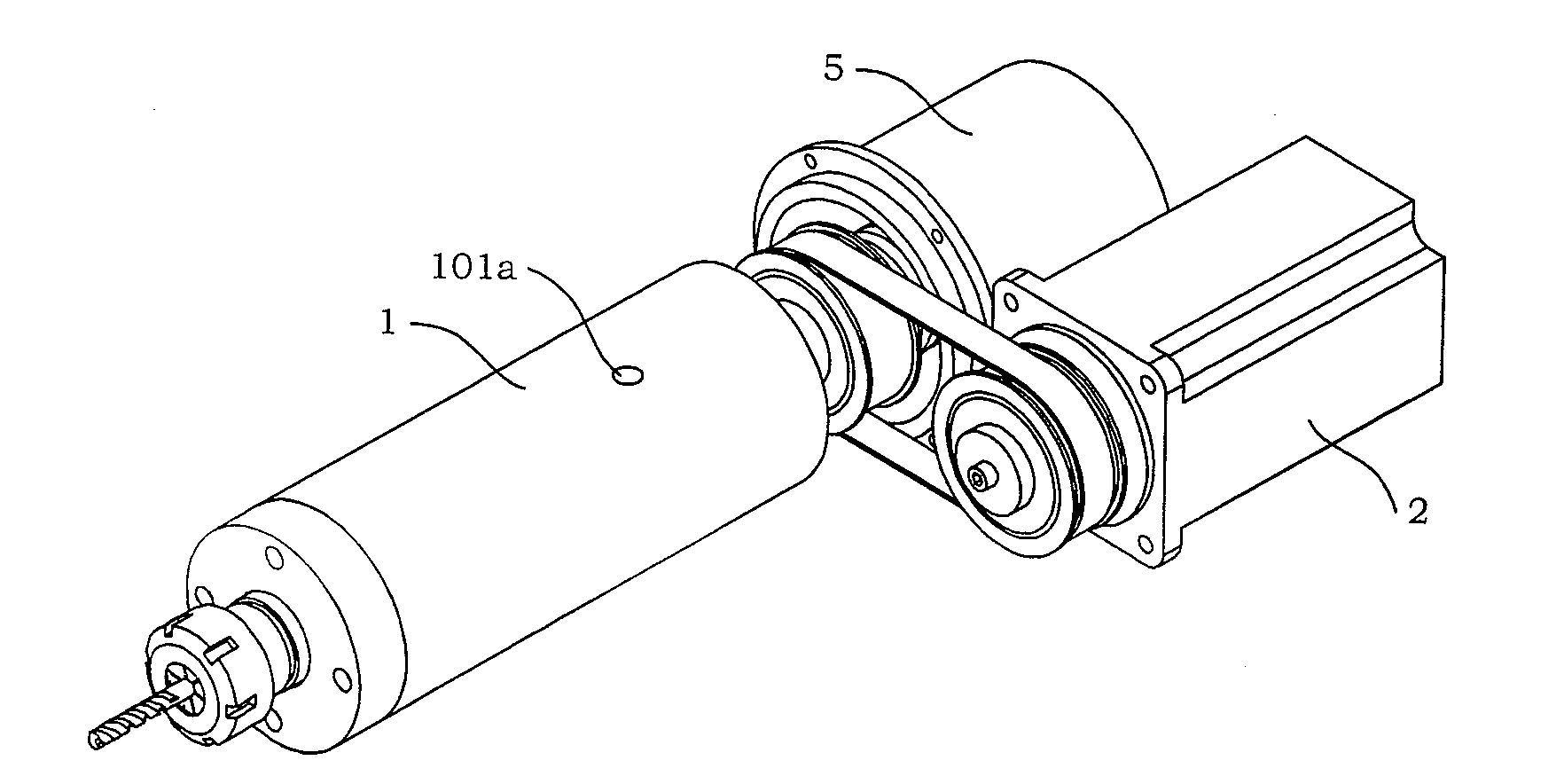
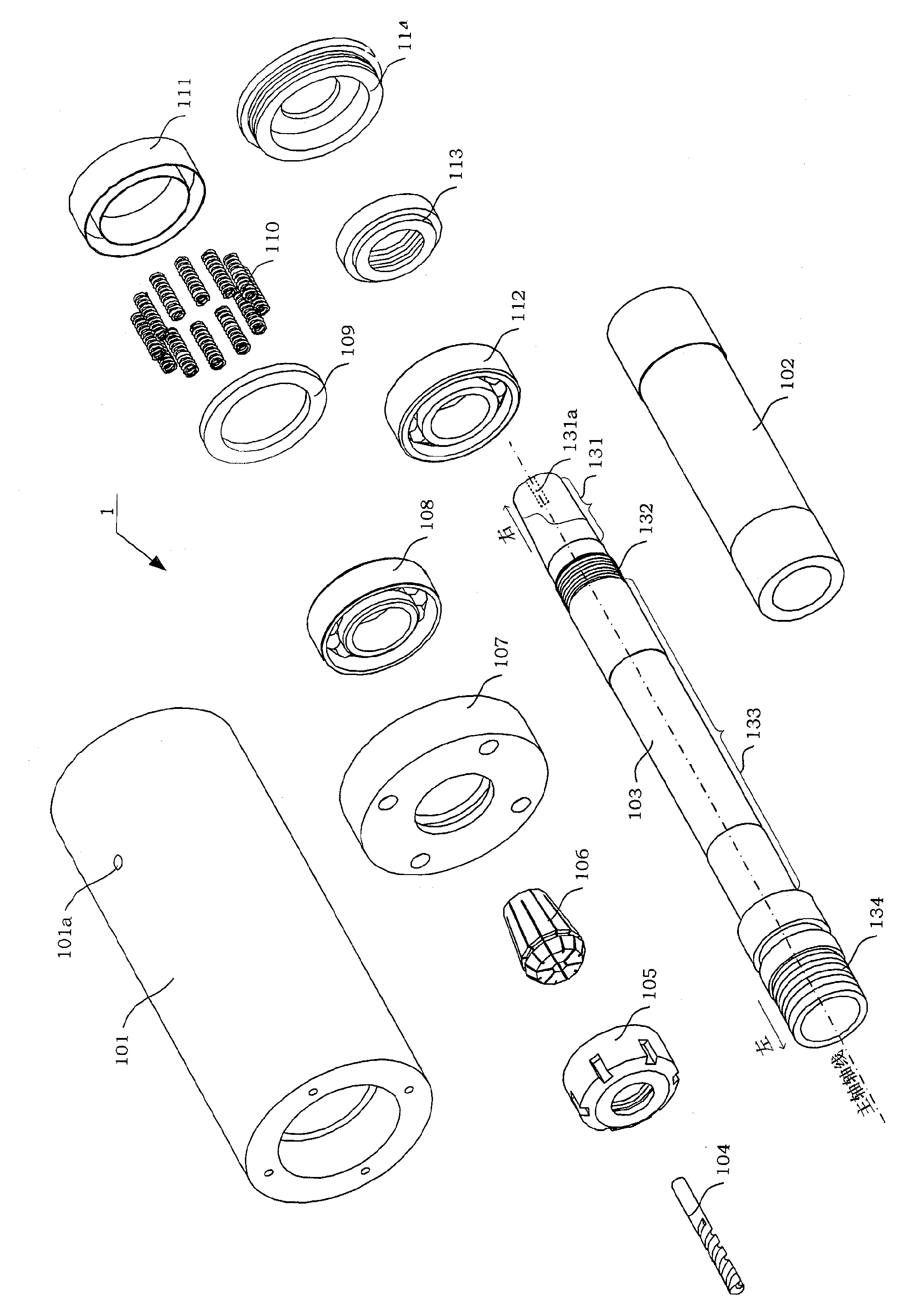
[0025] see figure 1 , Figure 1A , image 3 As shown, the present invention is a rotary transducer spindle device for ultrasonic vibration drilling. The rotary transducer spindle device is composed of a spindle assembly 1, a motor drive assembly, a transducer power supply assembly 5, and a housing assembly; The compression screw 510 of the transducer power supply assembly 5 is connected in the threaded hole 131a of the main shaft 103 of the main shaft assembly 1; the driven pulley 32 of the motor drive assembly is sleeved on the main shaft 103 of the main shaft assembly 1, and the driving pulley 31 It is connected with the driven pulley 32 through the transmission belt 3.

[0026] see figure 1 As shown, the housing assembly includes a motor connection plate 4a, an upper housing 4c, a lower housing 4b, and a transducer cover 4e; the main shaft assembly 1 i...


PUM


Abstract

The invention discloses a rotary transducer spindle device for ultrasonic vibration drilling. The rotary transducer spindle device consists of a spindle assembly (1), a motor drive assembly, a transducer power supply assembly (5), and a housing assembly Composition; the compression screw (510) of the transducer power supply assembly (5) is connected in the threaded hole (131a) of the main shaft (103) of the main shaft assembly (1); the driven pulley (32) of the motor drive assembly is socketed On the main shaft (103) of the main shaft assembly (1), the driving pulley (31) and the driven pulley (32) are connected through a transmission belt (3). The spindle device of the rotary ultrasonic transducer of the present invention can be installed on a table-type drilling machine, and the workpiece can be processed by adding a feed control component. Make the motor in the system work, use the slip ring (502a) to supply power to the ultrasonic transducer, realize the high-speed rotation of the main shaft (103) and generate ultrasonic vibration in the axial direction of the main shaft, and superimpose to obtain the composite motion of the rotational ultrasonic vibration. Clamping a drill bit or reamer at the end of the spindle can realize rotary ultrasonic vibration drilling or reaming.

Description

technical field [0001] The invention relates to a spindle device, more particularly, a spindle device suitable for ultrasonic vibration drilling. The spindle device can generate rotary ultrasonic vibration, and belongs to metal cutting processing and metal cutting equipment components. Background technique [0002] Under the existing technical conditions, the most widely used and most practical method in the small hole processing of difficult-to-machine materials (such as glass, engineering ceramics, metal matrix composites, etc.) is the ordinary drilling process, but when this method is used, Drills are prone to deviation, poor centering, poor chip removal, difficult heat dissipation, and many exit burrs, which are difficult to meet the needs of small hole precision and ultra-precision machining. However, special processing methods (electric spark, laser, electron beam, ion beam, electrolysis, etc.) have poor hole roundness and aperture accuracy, poor surface roughness, exp...

Claims


Application Information

Patent Timeline
Patent Type & Authority Patents(China)
IPC IPC(8): B23B19/00B23B37/00B06B1/06
Inventor 张德远高正博马晓杰
Owner BEIHANG UNIV
Why Eureka
Try Eureka