Device and method for preparing aniline by nitrobenzene hydrogenation

A technology for preparing nitrobenzene and aniline, which is applied in the preparation of amino compounds, chemical instruments and methods, preparation of organic compounds, etc., can solve the problems of easy deactivation of catalysts, difficult temperature control, low safety, etc., and achieves a deactivation trend. The effect of slowing down, reducing production costs, and operating flexibility

Inactive Publication Date: 2007-08-15
TSINGHUA UNIV
View PDF0 Cites 34 Cited by
  • Summary
  • Abstract
  • Description
  • Claims
  • Application Information

AI Technical Summary

Problems solved by technology

[0007] The purpose of the present invention is aimed at existing nitrobenzene high-temperature vaporization feed hydrogenation (high energy consumption, difficult temperature control, easy deactivation of catalyst, limited fluidized bed capacity) and independent nitrobenzene low-temperature liquid-phase feed hydrogenation ( High liquid distribution requirements) the shortcomings of the two methods of preparing aniline, as well as the current high energy consumption and low safety of hydrogenation after the purification of nitrobe

Method used


Image

  • Device and method for preparing aniline by nitrobenzene hydrogenation
  • Device and method for preparing aniline by nitrobenzene hydrogenation
  • Device and method for preparing aniline by nitrobenzene hydrogenation

Examples


Embodiment 1

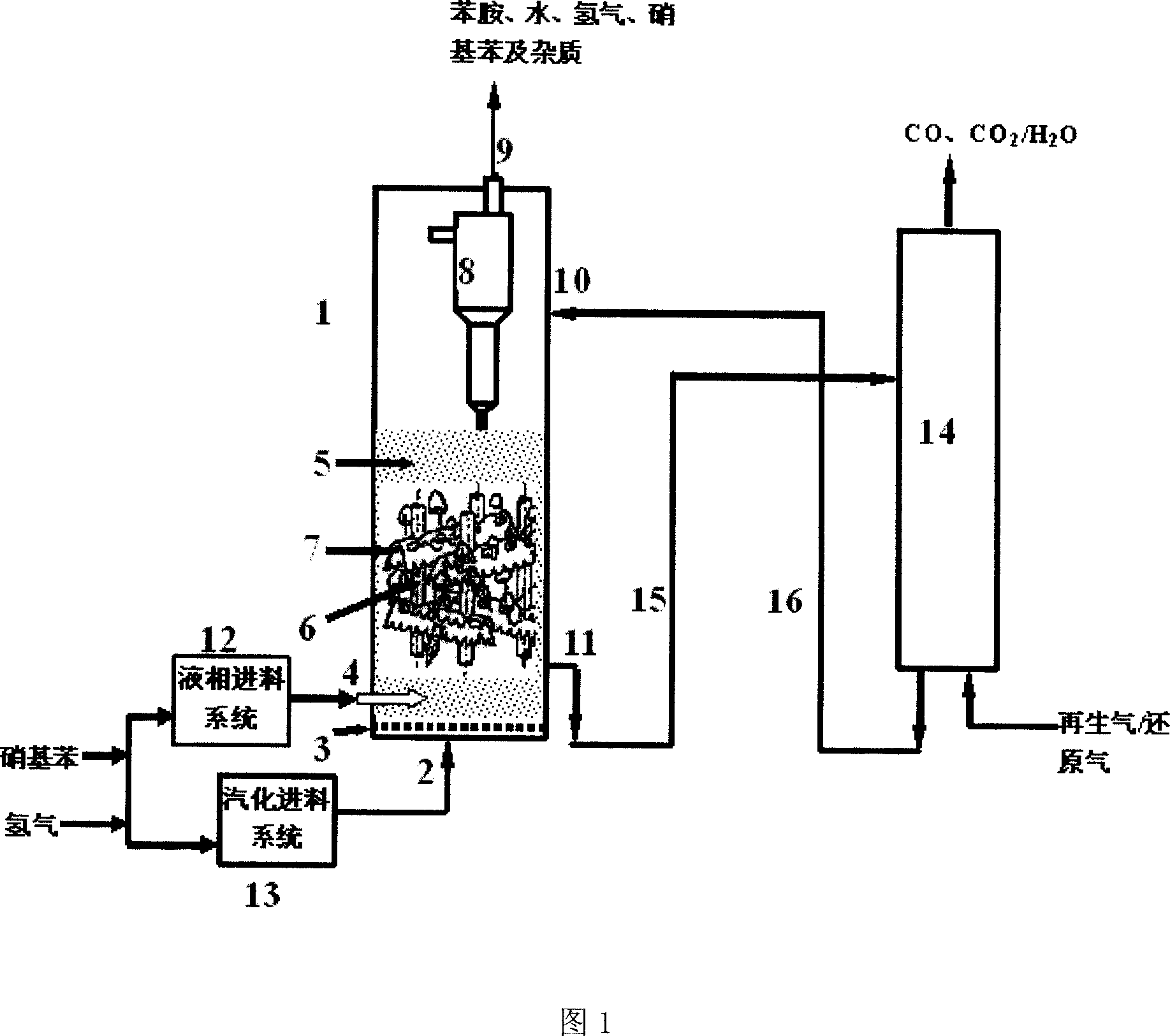
[0046] The gas inlet (2), gas distributor (3), heat exchange tube (10), gas-liquid double-flow nozzle (4), heat exchange tube (6), component (7), catalyst inlet (10), catalyst outlet (11), the cyclone separator (8) and the gas outlet (9) are sequentially connected with the cylinder wall of the fluidized bed (1) to form a complete fluidized bed (1). Wherein, the distance between the gas distributor (3) and the gas-liquid dual-flow nozzle (4) is 0.1 times the diameter of the fluidized bed. Four gas-liquid double-flow nozzles are uniformly distributed on the cylinder wall of the fluidized bed and extend into the fluidized bed.

[0047] The hydrogen and nitrobenzene pipelines of the nitrobenzene liquid-phase feeding system (12) are respectively connected to the gas pipeline and the liquid pipeline of the gas-liquid dual-flow nozzle (4). The nitrobenzene high-temperature vaporization feeding system (13) is connected with the fluidized bed gas inlet (2) and the gas distributor (3)....

Embodiment 2

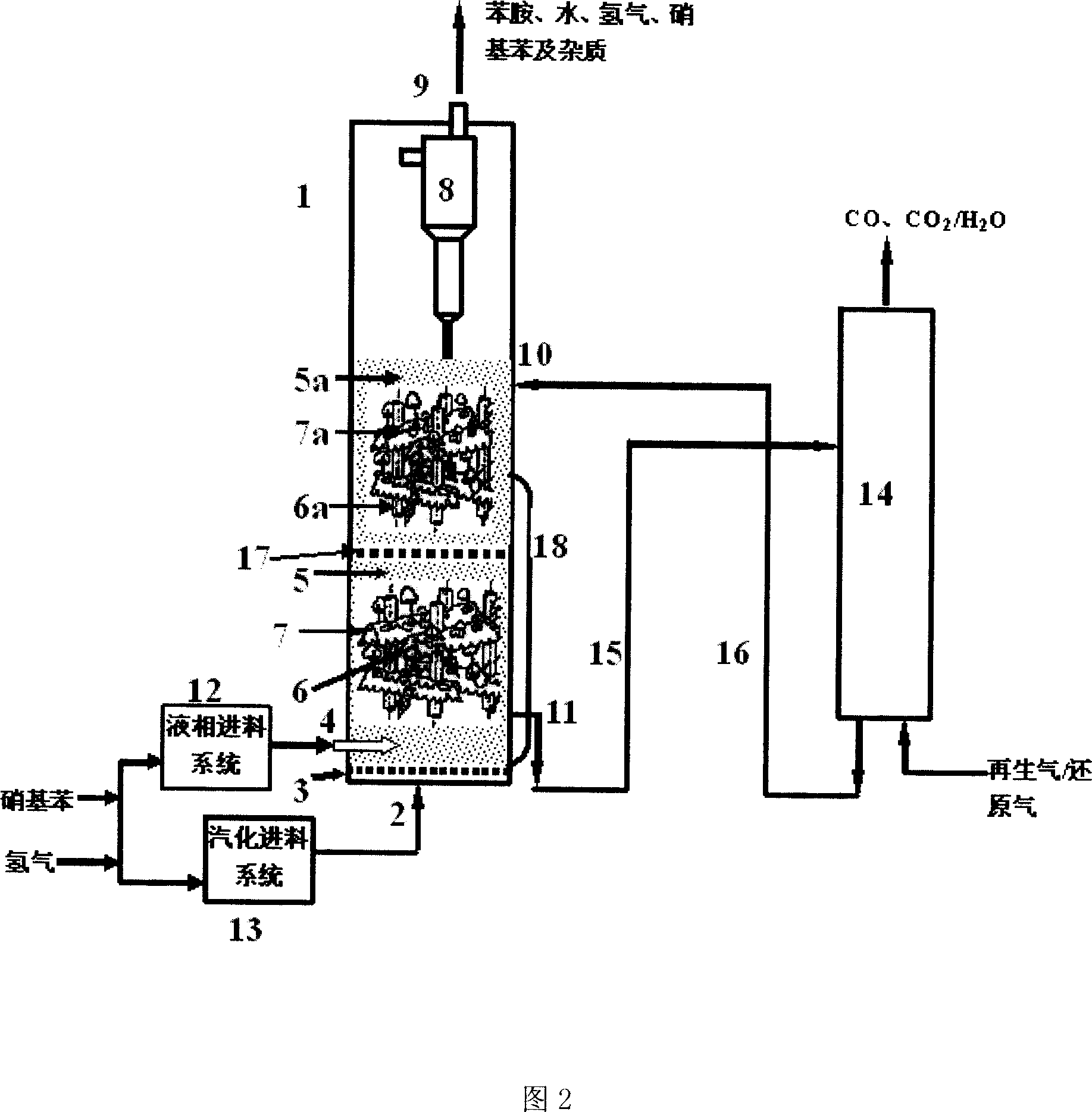
[0052] Gas inlet (2), gas distributor (3), heat exchange tube (10), gas-liquid double-flow nozzle (4), heat exchange tube (6, 6a), components (7, 7a), transverse porous distribution plate (17), transverse porous distribution plate (18), catalyst inlet (10), catalyst outlet (11), cyclone separator (8) and gas outlet (9) are connected to the cylinder wall of fluidized bed (1) successively, constitute Complete two-stage fluidized bed (1). Wherein, the distance between the gas distributor (3) and the gas-liquid dual-flow nozzle (4) is one time of the diameter of the fluidized bed. Eight gas-liquid double-flow nozzles are uniformly distributed on the cylinder wall of the fluidized bed and extend into the fluidized bed.

[0053]The hydrogen and nitrobenzene pipelines of the nitrobenzene liquid-phase feeding system (12) are respectively connected to the gas pipeline and the liquid pipeline of the gas-liquid dual-flow nozzle (4). The nitrobenzene high-temperature vaporization feedin...

Embodiment 3

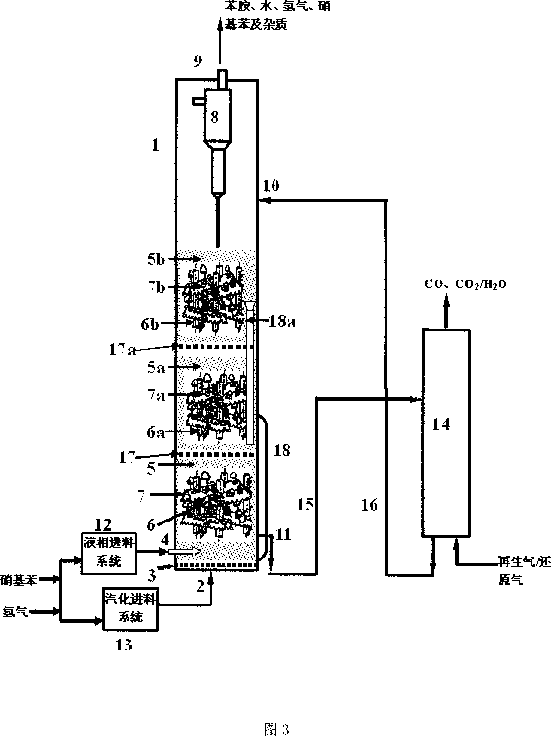
[0058] The gas inlet (2), gas distributor (3), heat exchange tube (10), gas-liquid dual-flow nozzle (4), heat exchange tube (6, 6a, 6b), components (7, 7a, 7b), Horizontal porous distribution plate (17, 17a), overflow pipe (18, 18a), catalyst inlet (10), catalyst outlet (11), cyclone separator (8) and gas outlet (9) are sequentially connected with fluidized bed (1 ) are connected to each other to form a complete three-stage fluidized bed (1). Wherein, the distance between the gas distributor (3) and the gas-liquid dual-flow nozzle (4) is 0.5 times the diameter of the fluidized bed. 16 gas-liquid double-flow nozzles are uniformly distributed on the cylinder wall circumference of the fluidized bed and extend into the fluidized bed.

[0059] The hydrogen and nitrobenzene pipelines of the nitrobenzene liquid-phase feeding system (12) are respectively connected to the gas pipeline and the liquid pipeline of the gas-liquid dual-flow nozzle (4). The nitrobenzene high-temperature va...


PUM


Abstract

The invention discloses a phenylamine making device and method hydrogenated by nitrobenzene in the chemical preparing technical domain, which comprises the following parts: fluid bed, gas distributor, gas-liquid double-flow sprayer, catalyst dense-phase area, heat-exchange device and component system, catalytic overflow pipe or inflow pipe, gasifying inlet system, liquid-phased inlet system and on-line regenerative device of catalyst, wherein each device connects entire inlet, reacting and catalyst regenerating reacting device; the catalyst is loaded in the fluid bed, which aerates little nitrogen or air to reduce; the composite gas with nitrobenzene and hydrogen is aerated into the reactor with impurity transmitted into phenylamine material nearly; the catalyst is returned to fluid bed through regenerative device, which guarantees continuous operation.

Description

technical field [0001] The present invention relates to a device and method for producing aniline by hydrogenation of nitrobenzene, in particular to a device and method capable of simultaneously realizing nitrobenzene liquid-phase feed and vaporization feed, and capable of realizing impurities containing high boiling points that are difficult to vaporize (such as dinitrogen) A device and a method for preparing aniline by continuous hydrogenation of nitrobenzene such as phenylbenzene, methylnitrobenzene, etc., belong to the technical field of chemical preparation. Background technique [0002] Aniline is a very important class of chemical products. With the wide application of polyurethane in the fields of construction, automobiles, electrical appliances and packaging materials, the output of methyl diisocyanate (MDI for short, prepared from aniline), the main raw material of polyurethane, has increased rapidly, resulting in a substantial increase in the consumption of anilin...

Claims


Application Information

Patent Timeline
IPC IPC(8): C07C211/46C07C209/36B01J8/24
CPCY02P20/584
Inventor 骞伟中魏飞王垚罗国华金勇汪展文
Owner TSINGHUA UNIV
Why Eureka
Try Eureka