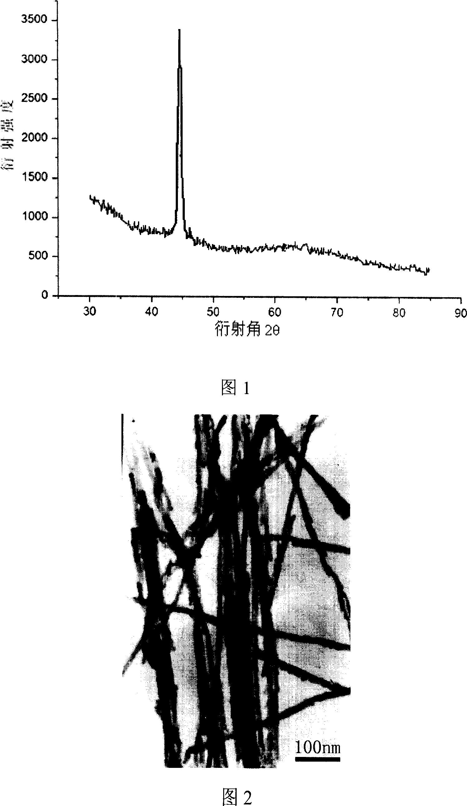
Method of preparing high square ratio magnetic one-dimensional nano line array
A technology of nanowire array and squareness ratio, which is applied in the field of preparation of electrochemical deposition by template method, can solve the problems of poor crystallinity of magnetic metal wires, unstable AC deposition process, and clogging of holes, so as to improve the coercive force , taking into account the effect of controllability and simple operation process
- Summary
- Abstract
- Description
- Claims
- Application Information
AI Technical Summary
Problems solved by technology
Method used
Image
Examples
Embodiment 1
[0025] 1. Preparation process of porous alumina template:
[0026] (1) Electrochemically polish the high-purity aluminum foil after degreasing and annealing
[0027] (2) Using 0.3M sulfuric acid solution as the dielectric, the oxidation voltage is 20V, and the anodic oxidation is 3hrs.
[0028] (3) Use a mixed solution of chromic acid and phosphoric acid to remove the formed aluminum oxide layer, wash it, and perform the second anodic oxidation under the same conditions as the first time.
[0029] (4) Gradually depressurize and thin the barrier layer: reduce the oxidation voltage by 2V each time for 30s until the voltage is reduced to 5V.
[0030] 2. Pulse Deposition Process
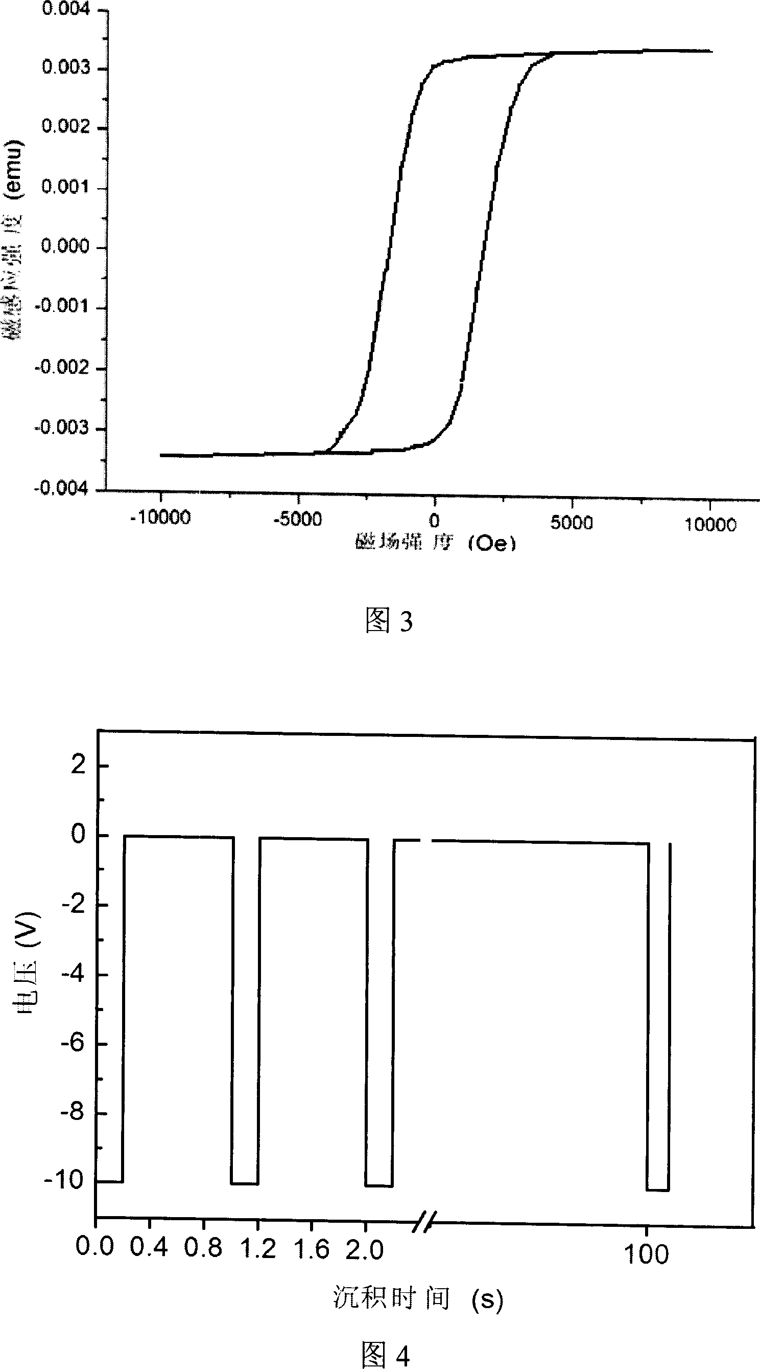
[0031] (1) Set the pulse voltage as shown in Figure 4. The local potential is 0V, the low potential is -10V, the ratio of high potential to low potential duration is 4:1, and the frequency is 1Hz.
[0032] (2) With porous alumina as the cathode, the metal salt solution to be plated is the electroplat...
Embodiment 2
[0036] 1. Preparation process of porous alumina template:
[0037] Concrete process is with embodiment 1.
[0038] 2. Pulse Deposition Process
[0039] (1) Set the pulse voltage as shown in Figure 4. The high potential is 0V, the low potential is -5V, the ratio of the duration of the high potential to the low potential is 4:1, and the frequency is 2Hz.
[0040] (2) Porous alumina is used as the cathode, and the metal salt solution to be plated is the electroplating solution, and the plating solution contains 200g / L cobalt sulfate and 20g / L boric acid. Graphite is the anode.
[0041] (3) The deposition time is controlled to be 20 mins to obtain a nanowire array with a length of about 3 μm.
[0042] The cobalt nanowire array obtained in Example 2 has a squareness ratio of 0.903 and a coercive force of 1547 Oe.
Embodiment 3
[0044] 1. Preparation process of porous alumina template:
[0045] Concrete process is with embodiment 1.
[0046] 3. Pulse deposition process
[0047] (1) Set the pulse voltage as shown in Figure 4. The high potential is 0V, the low potential is -8V, the ratio of the duration of the high potential to the low potential is 2:1, and the frequency is 5Hz.
[0048] (2) Porous alumina is used as the cathode, and the metal salt solution to be plated is the electroplating solution, which contains 300g / L nickel sulfate and 20g / L boric acid. Graphite is the anode.
[0049] (3) The deposition time is controlled to be 30 mins to obtain a nanowire array with a length of about 9 μm.
[0050] The cobalt nanowire array obtained in Example 3 has a squareness ratio of 0.905 and a coercive force of 802 Oe.
PUM
| Property | Measurement | Unit |
|---|---|---|
| diameter | aaaaa | aaaaa |
| length | aaaaa | aaaaa |
| length | aaaaa | aaaaa |
Abstract
Description
Claims
Application Information
 - R&D
- Intellectual Property
- Life Sciences
- Materials
- Tech Scout
- Unparalleled Data Quality
- Higher Quality Content
- 60% Fewer Hallucinations
Browse by: Latest US Patents, China's latest patents, Technical Efficacy Thesaurus, Application Domain, Technology Topic, Popular Technical Reports.
© 2025 PatSnap. All rights reserved.Legal|Privacy policy|Modern Slavery Act Transparency Statement|Sitemap|About US| Contact US: help@patsnap.com


