Vacuum heat insulation material

A technology of vacuum insulation materials and core materials, which is applied in heat exchange equipment, lighting and heating equipment, and pipeline protection through heat insulation, etc. It can solve the problems of reduced yield, low heat insulation, and reduced yield of vacuum insulation materials, and achieves Suppression of outgassing, excellent processability and handling, and excellent recyclability

Inactive Publication Date: 2007-08-22
株式会社三星日本研究所
View PDF6 Cites 24 Cited by
  • Summary
  • Abstract
  • Description
  • Claims
  • Application Information

AI Technical Summary

Problems solved by technology

[0012] Of course, chamfering the core material itself is also considered to improve the adhesion between the cladding material and the core material, but this requires chamfering the core material, which reduces the yield
Especially if it is an inorganic core material, the chamfering process itself is very complicated
[0013] In addition, the above-mentioned vacuum insulation materials are all produced by directly packing the core material into the outer packaging material, keeping the inside of the outer packaging material in a decompressed state, and sealing the opening of the outer packaging material at the same time, so there is a problem in the production efficiency of the vacuum insulation material.
That is, if the core material is directly packed into the outer packaging material, the outer packaging material is easily scratched, so the yield of the vacuum insulation mate

Method used

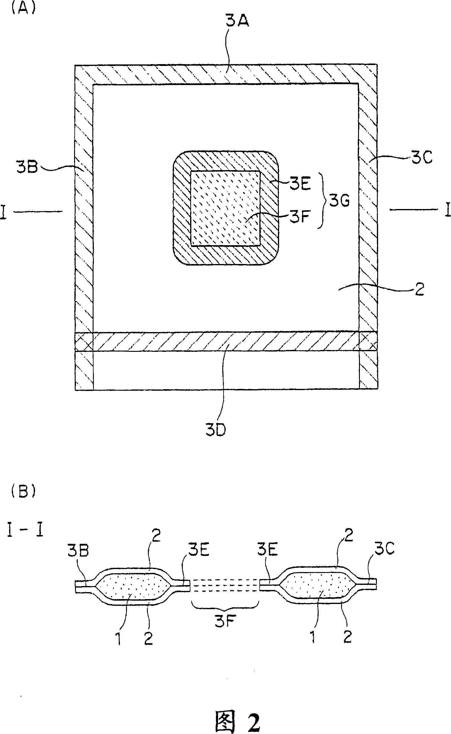
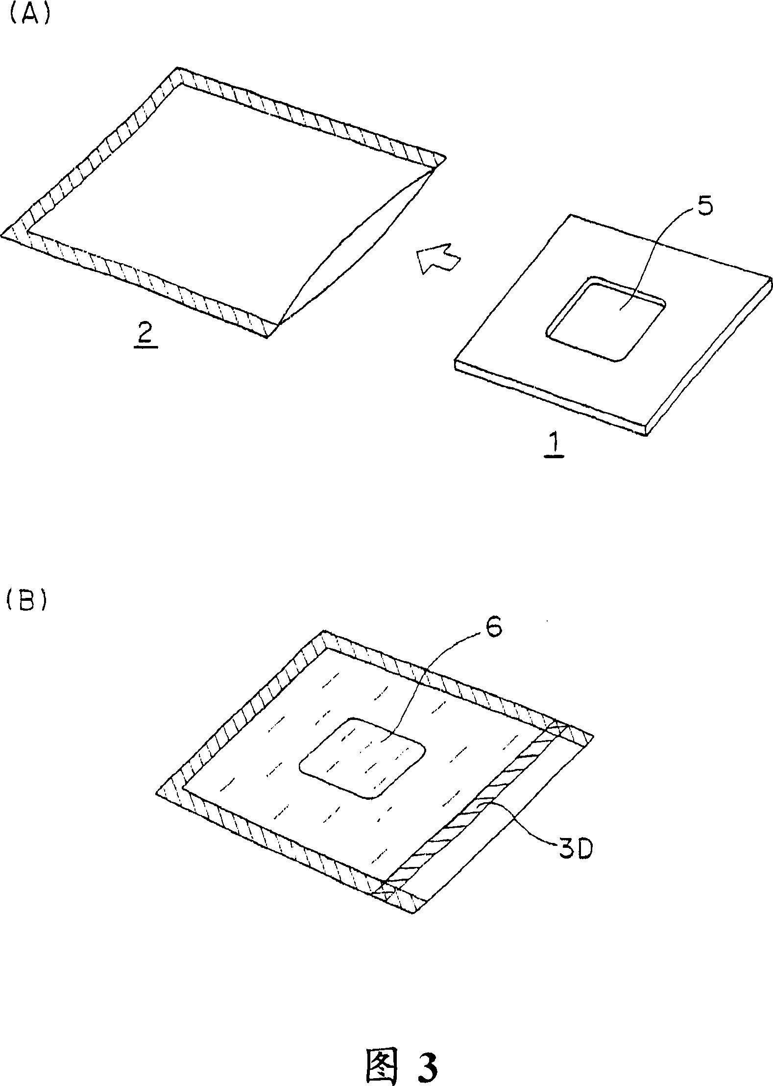

Image

  • Vacuum heat insulation material
  • Vacuum heat insulation material
  • Vacuum heat insulation material

Examples


Embodiment A

[0157]

[0158] The polyester fibers of Table 1 were used. All polyester fibers were polyethylene terephthalate fibers with a fiber length of 51 mm.

Embodiment A1

[0160] The polyester fibers in Table 1 were processed into sheets by a needle punching method. The weight per unit area of ​​the sheet just after processing is 550g / m 2 . This sheet was cut into a size of 200 mm×200 mm, and dried at a temperature of 120° C. for 1 hour. Four dried sheets were laminated, and the laminated material was used as a core material, and inserted into an outer packaging material made of a gas barrier film having a four-layer structure of nylon, aluminum-deposited PET, aluminum foil, and high-density polyethylene. Simultaneously, a gas adsorbent (manufactured by Saesugetta Izu Corporation: COMBO) was inserted into an outer packaging material. Then, vacuum was evacuated with a vacuum device to make the internal pressure 0.01 Torr, and sealing was performed by thermal fusion. The resulting vacuum heat insulating material had a size of 200mm×200mm and a thickness of 10mm. The core material density of the obtained vacuum insulation material is 220kg / m 3...

Embodiment A2-A8

[0161]

[0162] A vacuum heat insulating material was obtained in the same manner as in Example A1 except that the type and amount of fibers used for the core material were changed as shown in Table 1. In Comparative Example A2, it was not necessary to process into a sheet, and the fibers in the form of cotton wool could be used as they were.


PUM

PropertyMeasurementUnit
Average fiber diameteraaaaaaaaaa
Densityaaaaaaaaaa
Melting pointaaaaaaaaaa

Abstract

Disclosed is a vacuum heat insulation material which places very little burden on the environment during production and recycling processes. This vacuum heat insulation material has excellent handling properties and workability, and keeps providing good heat insulation for a long time. Specifically disclosed is a vacuum heat insulation material which is characterized by comprising at least a padding material and an envelope for holding the padding material which envelope is capable of maintaining the inside at a reduced pressure. The vacuum heat insulation material is also characterized in that the padding material is composed of a sheet-like fiber assembly containing not less than 50% by weight of polyester fibers having a fiber size of 1-6 denier.

Description

technical field [0001] The present invention relates to a vacuum insulation material that can be used as an insulation material for refrigerators, vending machines, refrigerators, refrigerated vehicles, hot water storage tanks, ice storage tanks, vacuum insulation piping, molded roof panels of automobiles, bathing pools, etc. Background technique [0002] Conventionally, insulation materials with various structures and performances have been used in refrigerators, vending machines, refrigerators, refrigerated vehicles, hot water storage tanks, ice storage tanks, vacuum insulation piping, molded roof panels of automobiles, and bathtubs. In recent years, vacuum heat insulating materials having very excellent heat insulating properties have been widely used in the above-mentioned applications. Vacuum heat insulating materials generally have a structure in which a core material is filled in an outer packaging material such as a gas-barrier metal vapor-deposition film, and the in...

Claims


Application Information

Patent Timeline
IPC IPC(8): F16L59/06F25D23/06B32B5/02
Inventor 高岛博之山下幸司
Owner 株式会社三星日本研究所
Why Eureka
Try Eureka