
Leakage-proof air-flue gaseous ring

A gas ring and airway technology, applied to piston rings, engine components, machines/engines, etc., can solve problems such as increased oil consumption, enlarged end clearance, and increased high-speed jet flow, so as to improve the average effective pressure and Thermal efficiency, elimination of high-speed jet effect, and reduction of oil consumption

Inactive Publication Date: 2007-09-05
张建元
View PDF0 Cites 2 Cited by
  • Summary
  • Abstract
  • Description
  • Claims
  • Application Information

AI Technical Summary

Problems solved by technology

[0003] At present, internal combustion engines generally use three gas rings. The thickness of the piston ring bank is small, and it is easy to break off along the whole ring of the bank root. If the height of the piston increases, the mass of the translation piece will increase, but the speed is difficult to increase, which limits the power increase.
[0004] At present, the internal combustion engine has an air leakage channel due to the gas ring. For a diesel engine, there is unburned or just-to-be-combusted fuel in the leaked air. For a gasoline engine, there is directly unburned fuel. These gases leak into the crankcase. It is crankcase exhaust gas. The concentration of harmful gases in crankcase exhaust gas is very high. It is not only an important source of pollution, but also makes the engine oil of the whole machine diluted by fuel, absorbing harmful gases and deteriorating. It cannot form an oil film and lose its lubricating effect. The pressure of the engine oil decreases, so after a period of use, the engine oil of the whole machine will be scrapped and new oil needs to be replaced. During this period of engine oil replacement, the machine wears the most seriously
[0005] At present, the internal combustion engine has air leakage due to the air leakage channel of the gas ring. Due to the high-speed jet flow and the flame running down, the oil at the opening of the ring is burned, and the heat released ignites the adjacent engine oil. The narrow gas between the cylinder, the ring and the plug is the circulating gas. , so that the air ring will produce friction under oil shortage at the opening, so that the temperature here will be high, resulting in melting friction, engine oil burning, increasing oil consumption, aggravating pollution, accelerating oil deterioration, and aggravating the air ring Air leaks at the opening, which increases the high-speed jet flow, forming a vicious circle
[0006] At present, due to the air leakage of the gas ring in the internal combustion engine, the engine oil enters the combustion chamber during the intake and exhaust process, and burns during the combustion process. The failure of the spark plug causes the small holes in the vortex chamber to be blocked, especially the carbon deposits in the piston ring groove, which makes the upper and lower sides of the piston ring groove uneven, destroys the second sealing surface, aggravates air leakage and oil channeling, and in severe cases, the gas ring will be glued. Stuck, broken, scratched, biting the cylinder, burning engine oil and emitting blue smoke, the pollution seriously exceeds the standard
[0007] As shown in Figure 8, if the current internal combustion engine uses a pressure-equalizing gas ring, the free-state curvature radius ρ' of the outer circumference of the ring is the largest at the opposite side of the ring opening, which is greater than the cylinder radius r, that is, ρ'>r, and the closer to the opening, the smaller ρ' , at the opening ρ′=r, it has been worn out, not only the end gap becomes larger, but also warped because the free-state curvature radius of the ring is smaller than the cylinder radius, and the original gas ring leaks light and air near the opening. Point air ring, cylinder liner is easy to lose round air leakage, and the manufacturing cost is high

Method used


Image

  • Leakage-proof air-flue gaseous ring
  • Leakage-proof air-flue gaseous ring
  • Leakage-proof air-flue gaseous ring

Examples


Embodiment 1

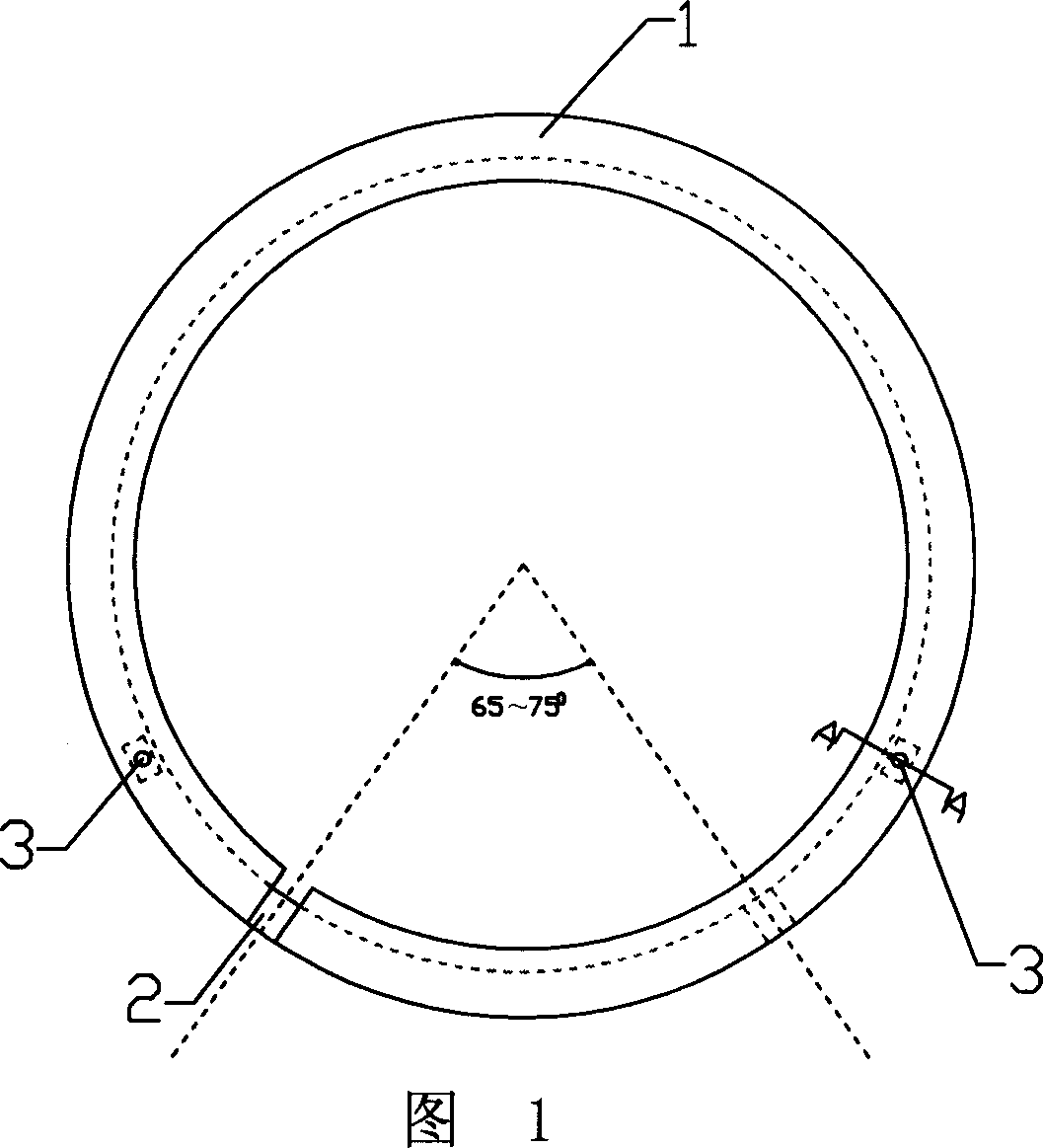
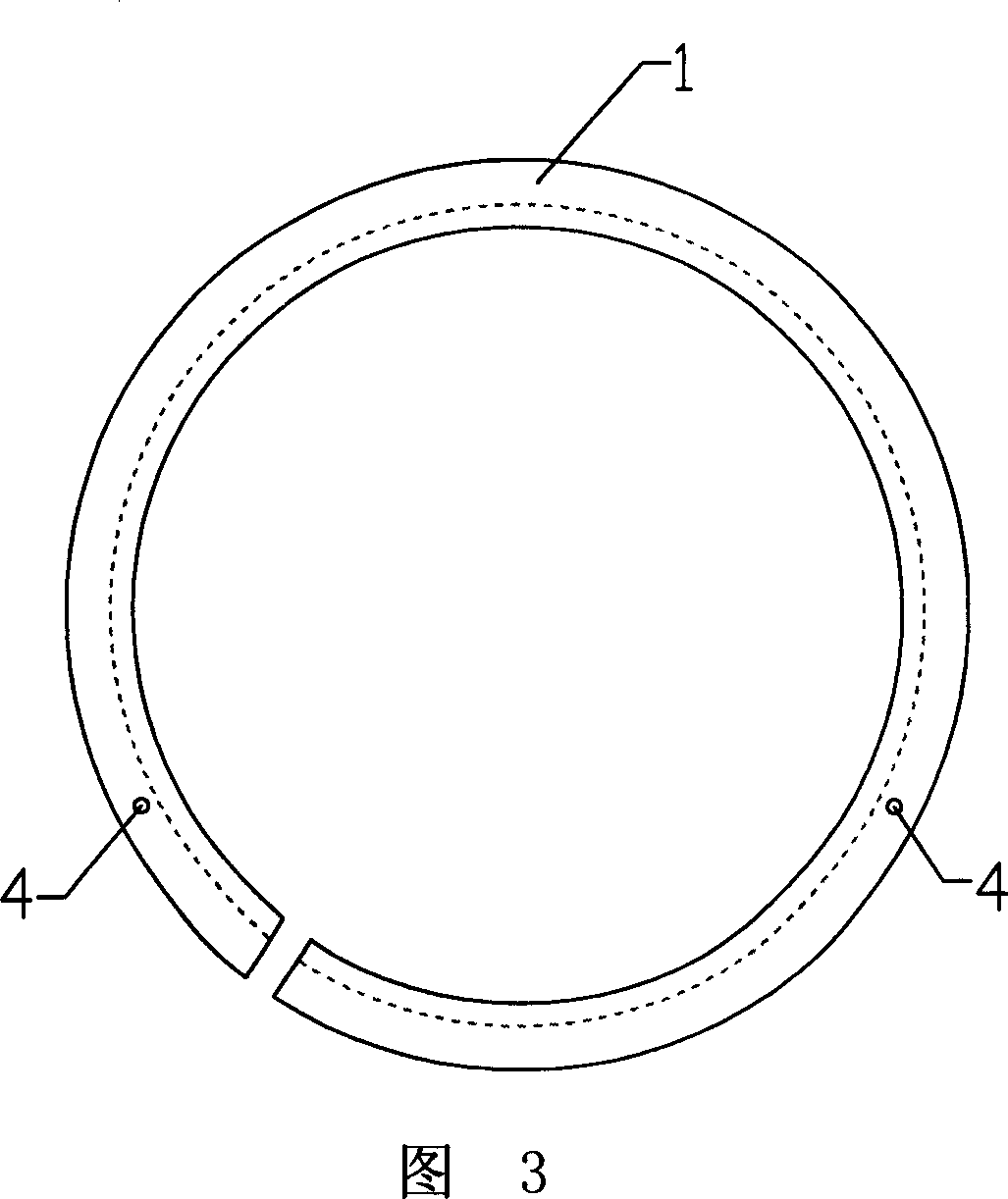
[0028] Embodiment 1, as shown in Fig. 1 and Fig. 2, a non-leakage air passage gas ring is used for sealing between the internal combustion engine piston and the cylinder block, and the non-leakage air passage air ring includes an upper ring 1 combined into one and the lower ring 2, as shown in Figure 3 and Figure 4, the section of the upper ring 1 is L-shaped, as shown in Figure 5 and Figure 6, the section of the lower ring 2 is rectangular, the upper ring 1 and the lower The rings 2 have openings respectively. The openings of the upper ring 1 and the lower ring 2 are set at an angle of 68°. The outer peripheries of the upper ring 1 and the lower ring 2 are closely matched and are on the same circumferential surface. The lower bottom surfaces of the rings 2 are closely matched and are on the same plane. Since the openings of the upper and lower rings are staggered and blocked from each other, the air leakage path is eradicated, the amount of air leakage is reduced, and the aver...

Embodiment 2

[0030] Embodiment 2, as shown in Fig. 1 and Fig. 2, a non-leakage air passage gas ring is used for sealing between the piston and the cylinder block of an internal combustion engine, and the non-leakage air passage air ring includes an upper ring 1 combined and the lower ring 2, as shown in Figure 3 and Figure 4, the section of the upper ring 1 is L-shaped, as shown in Figure 5 and Figure 6, the section of the lower ring 2 is rectangular, the upper ring 1 and the lower The rings 2 have openings respectively. The openings of the upper ring 1 and the lower ring 2 are set at an angle of 73°. The outer peripheries of the upper ring 1 and the lower ring 2 are closely matched and are on the same circumferential surface. The lower bottom surfaces of the rings 2 are closely matched and are on the same plane. Since the openings of the upper and lower rings are staggered and blocked from each other, the air leakage path is eradicated, the amount of air leakage is reduced, and the average...


PUM


Abstract

This invention discloses a gas-proof gaseous ring used as the seal between piston and cylinder body of the internal-combustion engine. This gaseous ring includes the upper ring that shapes L and nether ring that is rectangle. The two rings have separate openings set up with 65- 75degree. Since the place of the openings is mutually staggered and stuffed, this eradicates air loss passage and lowers the air leakage so as to improve the mean effective pressure and the thermal efficiency. With the simple structure and low manufacturing cost, this invention makes voltage-sharing to the cylinder wall and reduces the abrasion of the cylinder which prolongs the life expectancy of the cylinder body.

Description

technical field [0001] The invention relates to a matching system for a piston of an internal combustion engine, in particular to a non-leakage gas ring capable of blocking the gas leakage channel at the opening of the gas ring of the internal combustion engine. Background technique [0002] At present, there is always an air leakage channel at the opening of the gas ring of the internal combustion engine, and the total air leakage accounts for about 0.2-1% of the intake air volume, and the loss of average effective pressure and thermal efficiency is greater than 0.2-1%. [0003] At present, internal combustion engines generally use three gas rings. The thickness of the piston ring bank is small, and it is easy to break off along the whole ring of the bank root. If the height of the piston increases, the mass of the translator will increase, but the speed is difficult to increase, which limits the increase in power. [0004] At present, the internal combustion engine has an ...

Claims


Application Information

Patent Timeline
Patent Type & Authority Applications(China)
IPC IPC(8): F02F5/00
Inventor 张建元
Owner 张建元
Learn More