Array giant magnetic impedance effects current sensor

A current sensor and giant magneto-impedance technology, applied in the field of current measurement devices, can solve the problems of expanding the measurement range, low noise, etc., and achieve the effects of simple electronic circuit, improved signal-to-noise ratio, and improved linearity

Inactive Publication Date: 2010-05-19
JILIN UNIV
View PDF4 Cites 3 Cited by
  • Summary
  • Abstract
  • Description
  • Claims
  • Application Information

AI Technical Summary

Problems solved by technology

[0004] The purpose of the present invention is to provide a kind of array type giant magnetoimpedance effect current sensor based on the giant magnetoimpedance (GMI) effect design that amorphous soft magnetic strip has, and it can well solve the problem of making giant magnetoimpedance change rate and The magnetic field generated by the detected current has one-to-one correspondence, low noise, and the problem of expanding the measurement range; and the present invention has a simple structure, is economical and practical

Method used


Image

  • Array giant magnetic impedance effects current sensor
  • Array giant magnetic impedance effects current sensor
  • Array giant magnetic impedance effects current sensor

Examples


Embodiment 1

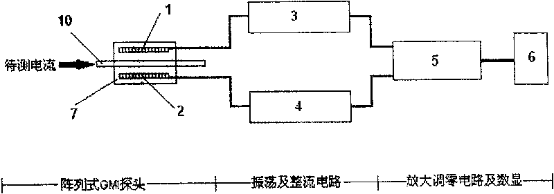
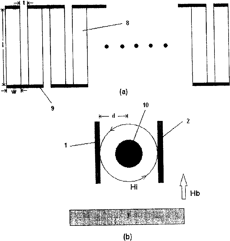
[0035] figure 2 Among them, 1 and 2 are arrayed amorphous current sensor probes, and 7 is a permanent magnet (such as ferrite, NdFeB, etc.), and block (cuboid) ferrite is used in the specific example. 8 is an amorphous strip unit, 9 is a copper wire, and 10 is a copper wire passing a current to be measured.

[0036] Array type amorphous current sensor probe 1 and array type amorphous current sensor probe 2 are respectively welded by 16 rectangular amorphous strip units 8 with good soft magnetic properties and copper wires 9 in series, and the length of amorphous strip unit 8 is 10mm , 2.5mm wide, 30um thick, the distance between the two amorphous strip units is 1mm, and the array type amorphous current sensor probe 1 and the array type amorphous current sensor probe 2 have the same requirements, symmetrically placed on both sides of the current conducting wire 10, When the current passes through the wire 10, a circular magnetic field H is generated around the wire i . The o...

Embodiment 2

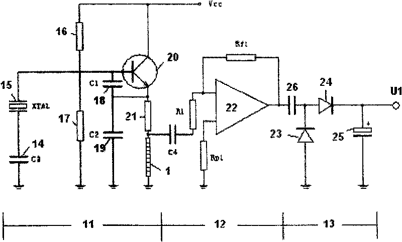
[0041] image 3 Among them, 1 is an array type amorphous current sensor probe, 11 is a Colpitts oscillator circuit, 12 is a preamplifier circuit, and 13 is a rectifier circuit. 14 is the starting capacitor C 3 , 15 is the crystal oscillator, 16 and 17 are two voltage divider resistors with equal resistance, and 18 is the feedback capacitor C 1 , 19 is the feedback capacitor C 2 , 20 is a transistor, 21 is an emitter current limiting resistor, 22 is a high-frequency operational amplifier, 23, 34 are two rectifier diodes, 25 is a voltage stabilizing capacitor, and 26 is a filter capacitor.

[0042] The power supply voltage Vcc of the Corbitz oscillation circuit 11 can be 12V, and the static operating point of the base of the transistor 20 is designed to be stable. Since the resistance values ​​of the two divider resistors 16 and 17 are equal, the static operating voltage of the base of the transistor 20 is 6V. , the transistor 20 emitter static operating voltage is stable at ...

Embodiment 3

[0051] An embodiment of the data of each part of the circuit element is given.

[0052] image 3 Among them, the transistor 20 uses a high-frequency transistor of the type 2SC1815, and its cut-off frequency f T 5 times higher than crystal oscillator 15 frequency. The frequency of the crystal oscillator 15 is above 1 MHz, and the starting capacitor 14 is 15 pF˜10 nF, which can start the oscillation. The two voltage dividing resistors 16 and 17 can be selected as 10kΩ; the injector current limiting resistor 21 is 390Ω; the feedback capacitor 18 is 1000pF-2200pF, the feedback capacitor 19 is 60pF-200pF, and the ratio of the feedback capacitor 18 to the feedback capacitor 19 is 2 to 25 between. The oscillating frequency of the Corbitz oscillating circuit is the frequency of the crystal oscillator 15 .

[0053] image 3 In the preamplifier circuit 12, the gain-bandwidth product GBP should be selected as a high-frequency operational amplifier with a gain-bandwidth product GBP t...


PUM


Abstract

The present invention pertains to the field of current measuring device, and especially relates to a un-contact type sensor measuring the current by generating the change of the magnetic field throughthe current based on the Giant Magnetic Impedance (GMI) effect. Said sensor consists of an array type un-crystal GMI current sensor probe heads (1) and (2), a periodic circuit (3), a rectification circuit (4), a subsequent zeroing amplifier (5) and a digital display unit (6); the array type un-crystal GMI current sensor probe heads (1) and (2) are formed by welding a plurality of quadrate un-crystal band units (8) with good property of soft magnetism by the copper wires arranged in series and the two array type probe heads (1) and (2) which have a same requirement are laid on the two sides ofthe lead (10) for electrifying. The device has a differential type structure of two probe heads, and can amplify the signals and improve the signal to noise ratio and the degree of the linearity of the output curve; the device has a small structure and a high sensitivity and is economical and practical; the device can be used widely in each production and research field for the measuring of the current.

Description

technical field [0001] The invention belongs to the technical field of current measuring devices, in particular to an array type giant magneto-impedance (GMI) effect current sensor. Background technique [0002] Current measurement is an important issue in various fields of production and scientific research. Now many new technologies and materials are applied to current measurement devices. The most commonly used current sensors are transformer-type current sensors, Rogowski coils, shunt resistors, and Hall (Hell) element current sensors, etc., but these sensors have certain defects. The transformer-type current sensor and the Rogowski coil measure the current, requiring particularly precise coil winding, high signal processing requirements, and can only be used for the measurement of AC current; the shunt resistance can measure AC and DC current, but it is only a The resistance consumes a lot of power; the output signal of the Hall device changes little, and there is a ce...

Claims


Application Information

Patent Timeline
Patent Type & Authority Patents(China)
IPC IPC(8): G01R19/00
Inventor 张涛韩冰汤新岩张可任欢赵学枰岳鑫隆黄东岩
Owner JILIN UNIV
Why Eureka
Try Eureka