
Bilateral opposite flushing inlet wet ammonia method for flue gas desulfurizing technology and device thereof

A technology of desulfurization device and desulfurization process, applied in separation methods, chemical instruments and methods, and separation of dispersed particles, which can solve problems such as unfavorable reactions, low mass transfer efficiency, unfavorable spray tower gas-liquid mass transfer, etc., to achieve improved desulfurization Efficiency, elimination of dead corners of flue gas, and simple process flow

Inactive Publication Date: 2007-10-17
WUHAN KAIDI ELECTRIC POWER ENVIRONMENTAL
View PDF2 Cites 20 Cited by
  • Summary
  • Abstract
  • Description
  • Claims
  • Application Information

AI Technical Summary

Problems solved by technology

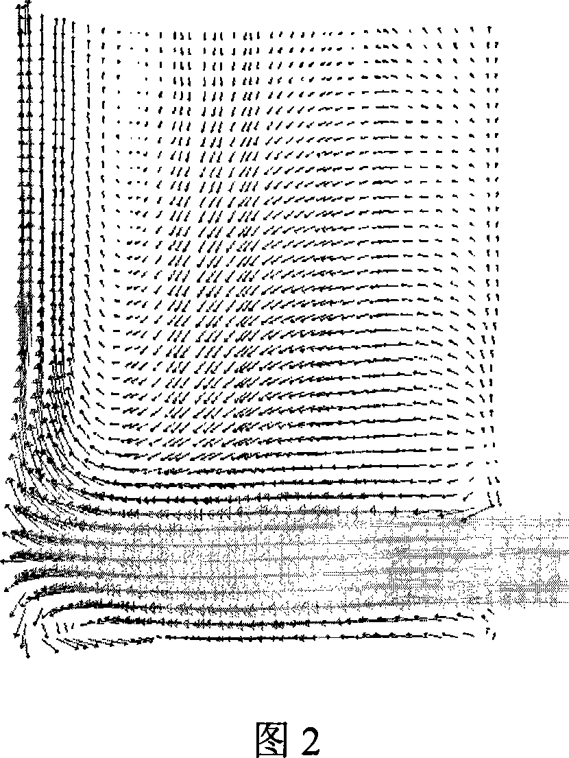
For the problem of low mass transfer efficiency caused by the flue gas flow in the desulfurization tower, most of the traditional methods use the single-side air intake method of the spray tower, and the part of the flue gas that reaches the outlet cross-section is refluxed through the pressure constraint of the spray tower outlet cross-section , forming a clockwise or counterclockwise large vortex in the upper part of the entire desulfurization tower, and relying on the rectification of desulfurizer droplets to make the flue gas flow field tend to be uniform
However, the flue gas flow field at this time is not conducive to the gas-liquid mass transfer in the spray tower, which is not conducive to the reaction between sulfur dioxide in the flue gas and the desulfurizer

Method used


Image

  • Bilateral opposite flushing inlet wet ammonia method for flue gas desulfurizing technology and device thereof
  • Bilateral opposite flushing inlet wet ammonia method for flue gas desulfurizing technology and device thereof
  • Bilateral opposite flushing inlet wet ammonia method for flue gas desulfurizing technology and device thereof

Examples


Embodiment Construction

[0032] The following is a further detailed description of the process of the present invention and its device for the discharged flue gas of a coal-fired boiler unit in conjunction with the accompanying drawings:

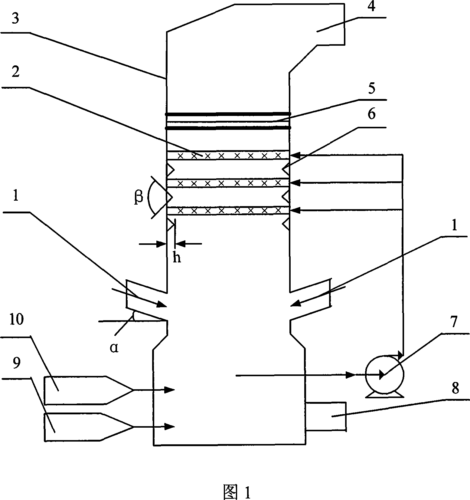
[0033] The wet-type ammonia flue gas desulfurization device with double-sided hedging intake shown in Figure 1 has a desulfurization tower 3, the bottom of the desulfurization tower 3 is provided with a desulfurization by-product discharge port 8, and the top of the desulfurization tower 3 is provided with The clean flue gas outlet 4 and the desulfurization tower 3 are sequentially provided with a bottom desulfurizer slurry tank area, a lower flue gas input area, a middle flue gas diversion and desulfurizer spray area, and an upper flue gas demisting area from bottom to top. The desulfurization agent pulp pool area at the bottom of the desulfurization tower 3 is connected with an ammonia water supply device 10 and an air feed device 9 . Downwardly inclined flue gas ...


PUM


Abstract

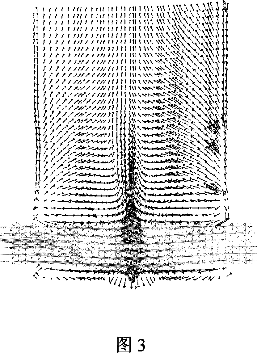
A wet ammonia method flue gas desulfurization process of two-side opposed inlet and device thereof, which makes the flue gas to form uniform upward opposed turbulence, then makes the flue gas to pass through flue gas antivortex baffle and ammonia desulfurizer cycle spraying layer which are staggered arranged to rapidly transmute the sulfur dioxide in the flue gas to be ammonium salt admixture, lastly, oxidates the ammonium sulfite in the ammonium salt admixture to be ammiaonia sulfate and outputs the clear flue gas after demisted. The device comprises an ammonia replenishment system and an air feeding device at the bottom of the thionizer, an opposed flue gas inlet at the lower of the thionizer, flue gas antivortex baffle and ammonia desulfurizer cycle spraying layer interleaving mounted at the middle of the thionizer, and a demister at upper of the thionizer, wherein the bottom of the thionizer is connected with the ammonia desulfurizer cycle spraying layer by cycle pump, the process and the device can improve the flue gas flow field effectively, enhance the gas-liquid mass transfer, and largely raise the desulfurization and the utilance of desulfurizer at the precondition without increasing the thionizer resistance and the consume of desulfurizer.

Description

technical field [0001] The invention relates to a purification treatment technology for flue gas discharged from a coal-fired power station, in particular to a wet-type ammonia flue gas desulfurization process and a device thereof. Background technique [0002] Coal is the main fuel for power stations in China at present and for a long period of time in the future. While pulverized coal combustion provides the necessary heat and power resources, it will also bring serious sulfur dioxide SO 2 pollute. According to relevant reports, the total discharge of sulfur dioxide in my country in 2005 was as high as 25.49 million tons. The acid rain caused by sulfur dioxide discharge has brought huge losses to my country's ecological environment and industrial and agricultural production, making the acid rain area of ​​my country close to 40% of the country's land area. %, fundamentally controlling sulfur dioxide emissions is imminent. [0003] The flue gas ...

Claims


Application Information

Patent Timeline
IPC IPC(8): B01D53/50
Inventor 李雄浩韩旭徐志安徐尹生高翔鹏余福胜李瑞鑫朱敬
Owner WUHAN KAIDI ELECTRIC POWER ENVIRONMENTAL
Learn More