

Ethylene device quench oil viscosity reductant
An ethylene device and viscosity reducing agent technology, applied in the fields of hydrocarbons, chemical instruments and methods, organic chemistry, etc., can solve the problems of lack of dispersed and passivated metals, unsatisfactory viscosity reduction effect, etc., to improve the fractionation effect, use The method is simple and the effect of reducing scaling
- Summary
- Abstract
- Description
- Claims
- Application Information
AI Technical Summary
Problems solved by technology
Method used
Image

Examples
Embodiment 1
[0031] The phenolic antioxidant selects 2,6-di-tert-butyl p-cresol, the amine antioxidant selects 2-ethylhydroxylamine, and the phenolic antioxidant and the amine antioxidant are 4: 3 by weight Mixed in the same proportion as a polymerization inhibitor.
[0032] The dispersant is polyisobutylene succinimide with a molecular weight of 2,000.
[0033] As the metal deactivator, polymethylsiloxane with a molecular weight of 1,500 is selected.
[0034] The above-mentioned polymerization inhibitor, dispersant and metal deactivator were mixed evenly in a weight ratio of 3:1:1 to prepare the quenching oil viscosity reducer of this embodiment.
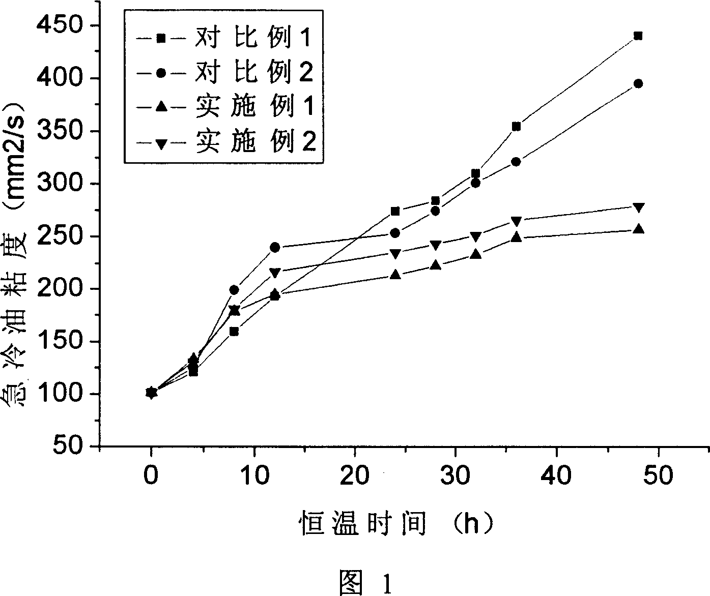
[0035]At a temperature of 200°C, 1000 grams of quenching oil sample (taken from the quenching system of the Yanshan ethylene plant) was added to the closed metal device, and the viscosity reducer of this embodiment was added in an amount of 500ppm (weight), and kept at a constant temperature for 48 hours , Take a sample every 4 hours to measu...
Embodiment 2
[0037] The phenolic antioxidant chooses 2,6-dimethyl-4-ethylphenol, the amine antioxidant chooses N,N'-di-tert-butyl-p-phenylenediamine, the phenolic antioxidant and the amine antioxidant The oxygen agent is mixed and prepared as a polymerization inhibitor in a weight ratio of 1:1.
[0038] The dispersant is polyisobutylene succinimide with a molecular weight of 2,000.
[0039] Dodecylbenzenesulfonic acid is selected as the metal deactivator.
[0040] The above-mentioned polymerization inhibitor, dispersant and metal deactivator were mixed evenly in a weight ratio of 3:1:1 to prepare the quenching oil viscosity reducer of this embodiment.
[0041] At a temperature of 200°C, 1000 grams of quenching oil sample (identical to Example 1) was added to a closed metal device without adding any viscosity reducer, kept at a constant temperature for 48 hours, and a sample was taken every 4 hours to measure the property of the quenching oil sample. kinematic viscosity. The test results...
Embodiment 3
[0048] This embodiment is to measure the thermal stability of the quenching oil viscosity reducer of the present invention.
[0049] The operating temperature of the circulating quenching oil is generally controlled below 220°C, but in the system, it will directly contact with the high-temperature cracking gas from the cracking furnace, and general chemicals will be decomposed to varying degrees. If the visbreaker is completely or mostly decomposed after one circulation with the quenching oil, the visbreaking effect will be lost. The decomposition temperature of the viscosity reducer of the present invention measured by DSC method (Differential Scanning Calorimetry, differential scanning calorimetry) is 350°C. Therefore, the possibility of the visbreaker decomposing under the quenching system is very small, and its visbreaking effect will not be affected.
PUM
 Abstract
Description
Claims
Application Information