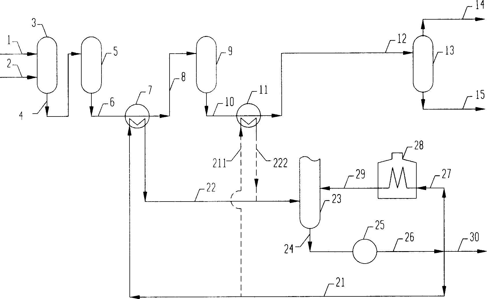
Method of recovering heat in hydrocarbon hydrogenating conversion process

A hydrogenation conversion and heat recovery technology, which is applied in lighting and heating equipment, heat generation by exothermic chemical reactions, heat generation by non-combustion exothermic chemical reactions, etc., can solve the problem of low preheating temperature of feedstock oil and reaction effluent Oversupply, increased investment and other issues, to achieve the effect of reducing the scale and investment of fractionation furnaces, saving fuel consumption, and reducing material grades

Inactive Publication Date: 2007-11-07
何巨堂 +1
View PDF0 Cites 25 Cited by
  • Summary
  • Abstract
  • Description
  • Claims
  • Application Information

AI Technical Summary

Problems solved by technology

The disadvantages of the heat recovery methods described above are:
[0003] ① The heat recovery method of the intermediate reaction effluent uses cold hydrogen or cold oil, which increases the scale of the cold hydrogen circulation system or increases the cold oil circulation system, which increases investment and converts high-temperature heat energy (such as 410-370°C heat energy) at the same time It is lower temperature heat energy (such as 410-50°C heat energy), of which 180-50°C heat energy cannot be recovered (usually cooled by air cooler or water cooler), and 410-180°C heat energy recovery process uses heat exchanger and intermediate reaction effluent Compared with direct use of heat exchangers, the investment in high-pressure heat exchangers is greatly increased due to the substantial reduction in temperature;
[0004] ②The heat recovery method of the final reaction effluent is to heat the raw material oil, hydrogen, low-fraction oil and excess heat energy to generate steam, but the heat energy utilization rate of the generated steam is lower than that of directly heating the process material or directly heating the reboiling liquid at the bottom of the fractionation tower
[0005] For the hydroconversion process of hydrocarbons with high hydrogen consumption, such as the hydroconversion process of coal tar or shale oil, due to the high hydrogen consumption and the large heat release of the reaction, there is a large amount of excess heat energy in the effluent in the middle of the reaction; The disadvantages of conventional hydroconversion process heat recovery methods are more obvious

Method used


Image

  • Method of recovering heat in hydrocarbon hydrogenating conversion process

Examples


Embodiment

[0056] The coal tar hydrogenation unit has a processing capacity of 62.5t / h. The properties of the coal tar are shown in Table 1, the operating conditions of the reaction part are shown in Table 2, and the embodiments of the present invention are shown in Table 3.

[0057] From the data listed in Table 3, it can be seen that:

[0058] ①Using the bottom oil of the fractionating tower as cold hot oil, recovering heat energy of 10.9MMkcal / h; saving 4,890 tons / year of standard fuel for the reboiler of the fractionating tower, worth 19 million yuan / year;

[0059] ② Save 29,100 standard cubic meters of hydrogen per hour, and reduce the investment in the hydrogen circulation system by about 6.5 million yuan;

[0060] ③Reduce the heat load of the reaction feed heating furnace by 4.20MMkcal / h, and reduce the investment by about 3 million yuan.

[0061]Although this embodiment takes a coal tar hydrogenation unit as an example, the features of the present invention shown by it are also ...


PUM

PropertyMeasurementUnit
boiling pointaaaaaaaaaa

Abstract

The present invention relates to method of recovering heat in hydrocarbon hydrogenating conversion process. The low temperature heat absorbing oil and the reaction resultant are heat exchanged to form high temperature heat absorbing oil, which enters to the bottom of the fractionating tower so as to mix with the liquid phase material flow inside the fractionating tower before being shunt into low temperature heat absorbing oil for reuse. The process is especially suitable for hydrogenating conversion of coal tar, and has the advantages of high heat utilizing rate, reduced hydrogen circulating system scale and reduced the scale of reboiling furnace in the fractionating tower. In addition, the heat absorbing oil heat exchanger may be used as the heater for starting the reactor or sulfurizing to reduce heat load of the heating furnace.

Description

technical field [0001] The invention relates to a heat recovery method in the hydrogenation conversion process of high hydrogen consumption hydrocarbons; in particular, the invention relates to a heat recovery method in the coal tar hydrogenation conversion process. Background technique [0002] As we all know, the hydroconversion process of hydrocarbon feedstock oil is the conversion process of hydrocarbon feedstock in the presence of catalyst and hydrogen, and is widely used in oil upgrading. The high-pressure separator hydrocarbon liquid produced by the hydroconversion process is composed of conventional liquid hydrocarbons and conventional gaseous hydrocarbons and non-hydrocarbon components such as H 2 S, H 2 O, NH 3 、H 2 and so on. Usually, the hydrocarbon liquid in the high-pressure separator first enters the low-pressure separator, and at a pressure of 0.5-4.0 MPa and a temperature of 35-60° C. 2 and C 1 、C 2 Low-partition gas composed of hydrocarbons and mainl...

Claims


Application Information

Patent Timeline
Patent Type & Authority Applications(China)
IPC IPC(8): C10G49/00F24J1/00F24V30/00
Inventor 何巨堂韩清霞
Owner 何巨堂
Why Eureka
Try Eureka