
End mill

An end mill and tool technology, applied in milling cutters, forming knives, milling machine equipment, etc., can solve problems such as difficulty in reducing processing efficiency and cost, wear or defect of end mills, and reduced chip discharge, etc. Effect of roughening, preventing roughening, and suppressing vibration

Inactive Publication Date: 2007-11-21
OSG
View PDF1 Cites 7 Cited by
  • Summary
  • Abstract
  • Description
  • Claims
  • Application Information

AI Technical Summary

Problems solved by technology

[0005] However, if the end mill is configured with unequal leads (unequal helix) or unequal divisions, the positional balance of the cutting edge or the chip discharge flute will deteriorate, so there is a problem that the chip discharge performance will be reduced.
In addition, as a result of the reduction in chip discharge performance, wear or chipping of the end mill easily occurs, and there is a problem that the tool life is shortened.
Moreover, these problems are more significant when performing high-speed cutting, and it is difficult to achieve both the improvement of processing efficiency and the reduction of costs.

Method used


Image

  • End mill
  • End mill
  • End mill

Examples


Embodiment Construction

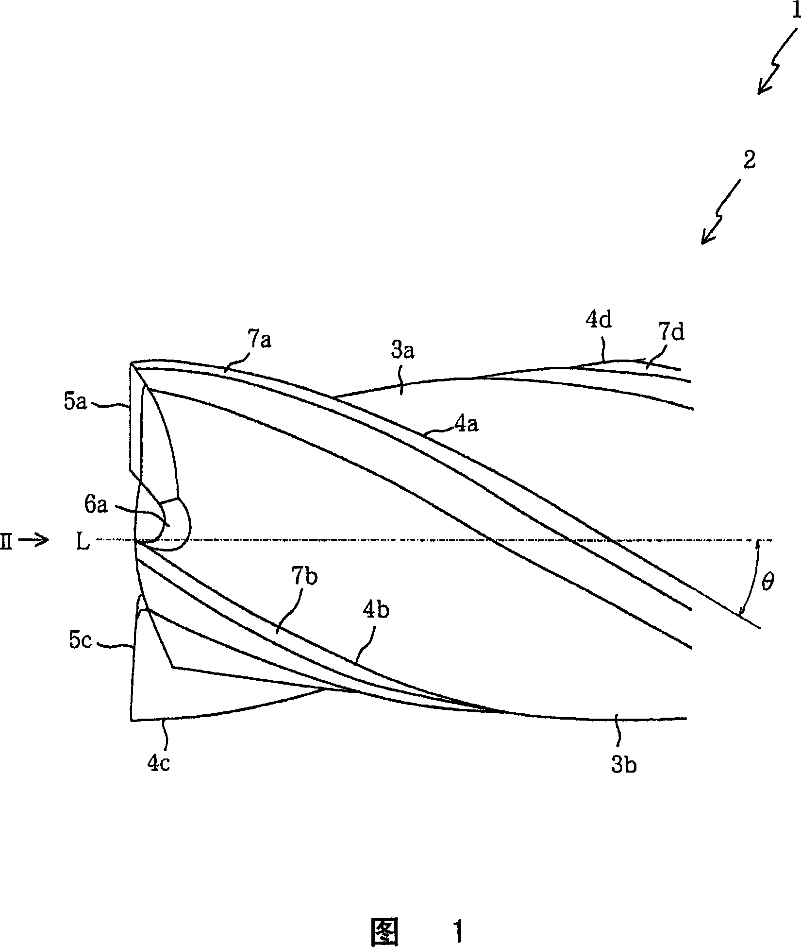
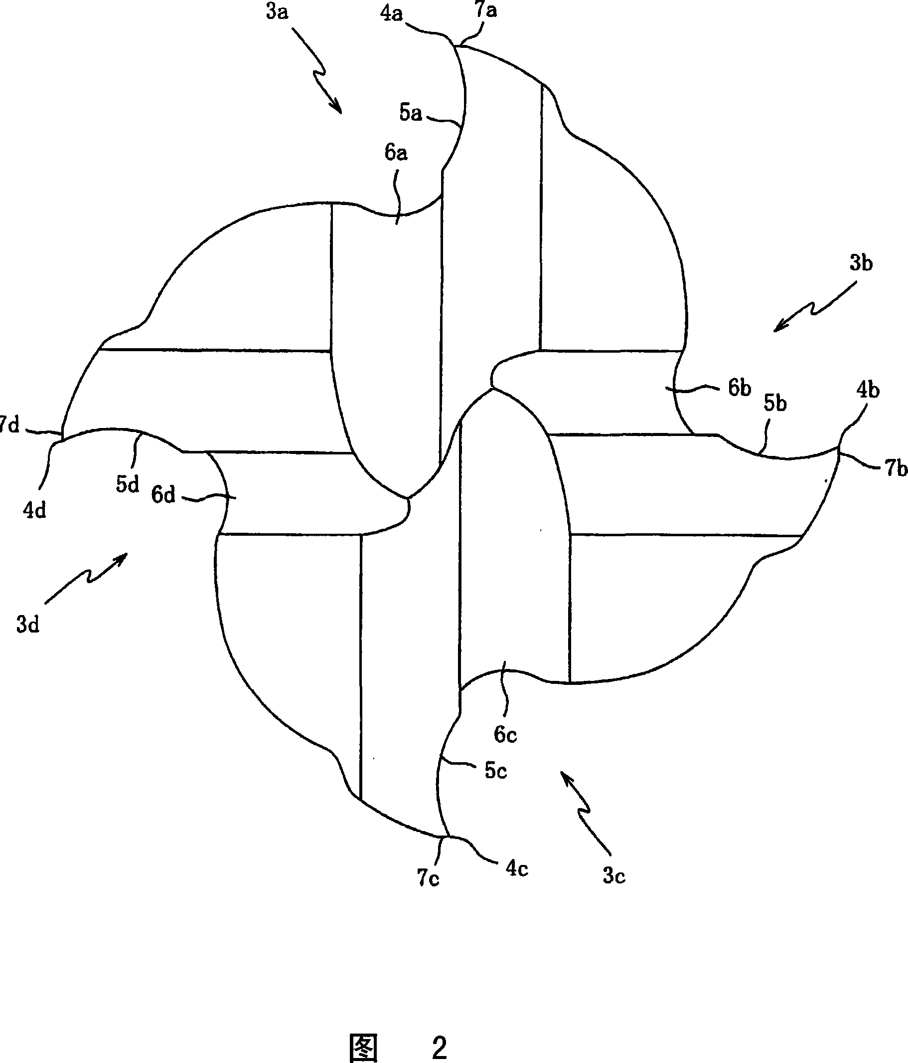
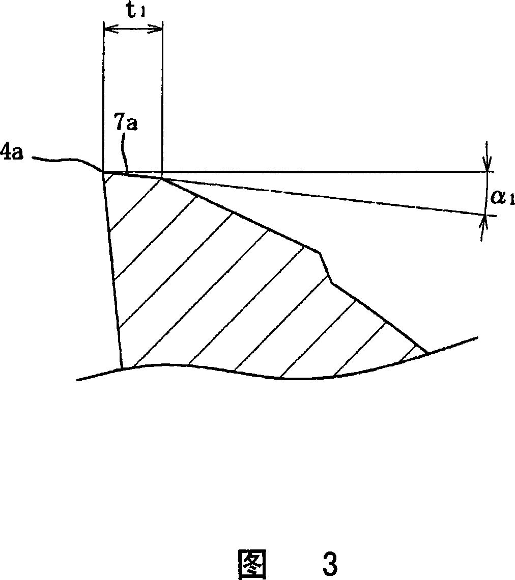
[0035] Hereinafter, embodiments of the present invention will be described based on the drawings. Fig. 1 is an enlarged front view of an end mill 1 according to an embodiment of the present invention, Fig. 2 is a side view of the end mill 1 viewed from the direction of arrow II in Fig. 1 , and Fig. 3 is a peripheral edge of the end mill 1 4a is a cross-sectional view at right angles to the axis. First, the overall structure of the end mill 1 will be described with reference to FIGS. 1 to 3 .

[0036] The end mill 1 is a solid square end mill including a tool body 2 having an axis L. As shown in FIG. The tool body 2 is made of cemented carbide after tungsten carbide (WC) is pressurized and sintered. ˜6d, the first relief surfaces 7a-7d of the peripheral cutting edges 4a-4d, and a cylindrical shank (not shown) formed on the other end side.

[0037] In addition, in this embodiment, titanium aluminum nitride (TiAlN) is coated on the peripheral cutting edges 4 a to 4 d and the b...


PUM


Abstract

The present invention provides methods and kits for determining the metabolic stability of compounds (e.g., stability to oxidative metabolism). In particular embodiments, the invention provides a method of determining the susceptibility of a compound to metabolism by an enzyme. In one representative embodiment, the enzyme is a cytochrome P450 enzyme. The invention is well-adapted for use in high throughput drug screening programs.

Description

technical field [0001] The present invention relates to an end mill, in particular to an end mill capable of suppressing vibration during cutting and having a long life. Background technique [0002] Generally, vibrations generated during cutting with an end mill cause roughening of the cut surface. Therefore, conventionally, as a technique for suppressing the vibration of an end mill with helical teeth (for example, a square end mill), unequal leads (unequal helixes) in which the helix angles of the helical teeth are different, or unequal helical pitches in which the helical teeth are arranged on the circumference have been proposed. Technology such as unequal division formed at unequal intervals in the direction. [0003] For example, Japanese Unexamined Patent Publication No. 63-89212 (Patent Document 1) discloses an end mill in which a plurality of cutting edges are helically unequal, and the end mill connected to the ends of these cutting edges On the front end face, ...

Claims


Application Information

Patent Timeline
Patent Type & Authority Applications(China)
IPC IPC(8): B23C5/10
CPCB23C5/10B23C2250/16B23C2210/0485B23C2210/0407B23C2210/44Y10T407/1948
Inventor 浜武恭生足立吉章大泽二朗
Owner OSG
Learn More