
Optical method and system for monitoring in-situ stress in use for epitaxial growth

A technology of epitaxial growth and in-situ stress, applied in chemical instruments and methods, crystal growth, single crystal growth, etc., can solve problems such as large noise and affecting the accuracy of stress monitoring, and achieve simplified image processing, improved precision, and elimination of system effect of error

Inactive Publication Date: 2007-12-26
SUZHOU INST OF NANO TECH & NANO BIONICS
View PDF0 Cites 3 Cited by
  • Summary
  • Abstract
  • Description
  • Claims
  • Application Information

AI Technical Summary

Problems solved by technology

[0005] In actual use, it is found that since the bandwidth of the GaN material is 365 nm, there will be relatively large noise during the measurement of the GaN material system, which affects the accuracy of stress monitoring

Method used


Image

  • Optical method and system for monitoring in-situ stress in use for epitaxial growth
  • Optical method and system for monitoring in-situ stress in use for epitaxial growth
  • Optical method and system for monitoring in-situ stress in use for epitaxial growth

Examples


Embodiment 1

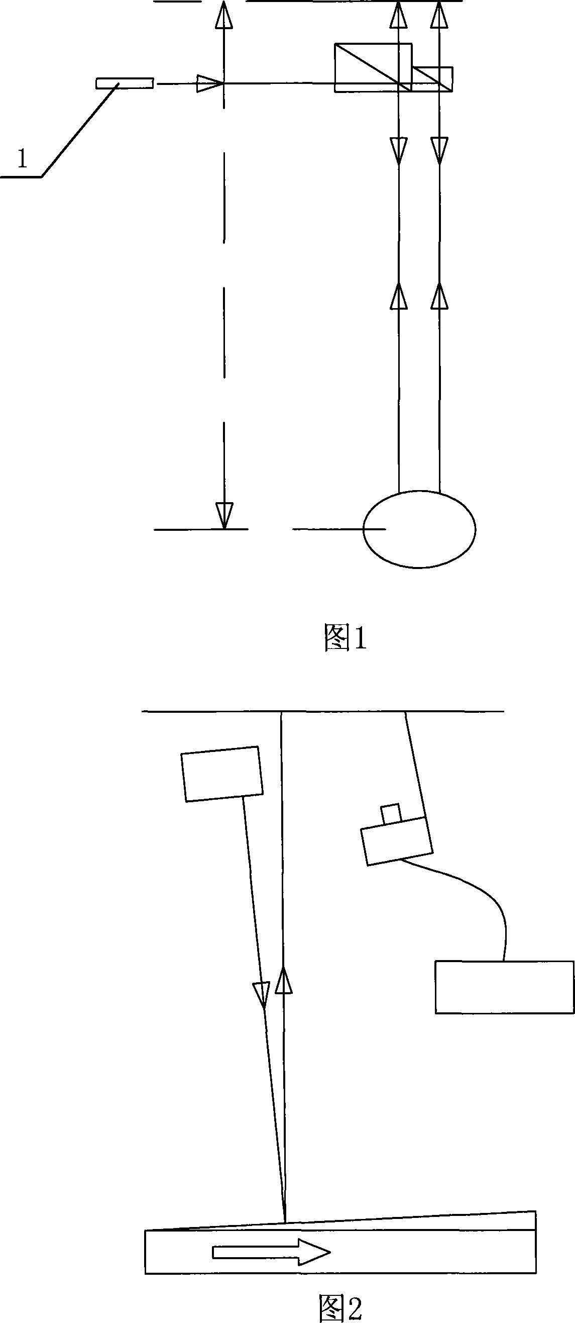
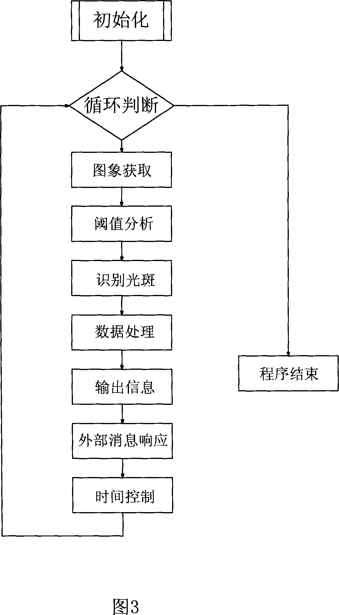
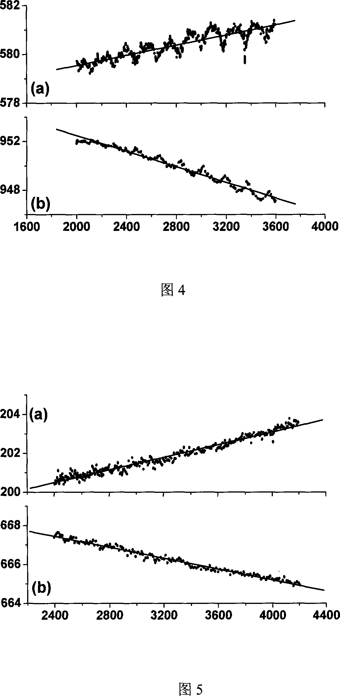
[0036] Embodiment 1: Referring to accompanying drawings 1 to 7, an in-situ stress optical monitoring system for epitaxial growth includes a laser 1, a laser beam splitter, an image acquisition device, a control system, and an optical system constituting a corresponding optical path. component, wherein the optical path is that the laser beam emitted by the laser is split into parallel laser beams by a laser beam splitter, and is incident on the surface of the epitaxial growth sheet to be tested through an optical element, and the reflected light is emitted through an optical element, forming an image On the image acquisition device, the wavelength of the laser is smaller than the wavelength corresponding to the bandwidth of the epitaxial growth sheet material to be tested. The image acquisition device is mainly composed of a projection board and a camera. In the optical path, the outgoing light is imaged on the projection board, and the light spot on the projection board is imag...

Embodiment 2

[0039] Embodiment 2: Referring to accompanying drawings 6 and 7, an in-situ stress optical monitoring system for epitaxial growth includes a laser 1, a laser beam splitter, an image acquisition device, a control system, and an optical system constituting a corresponding optical path. component, wherein the optical path is that the laser beam emitted by the laser is split into parallel laser beams by a laser beam splitter, and is incident on the surface of the epitaxial growth sheet to be tested through an optical element, and the reflected light is emitted through an optical element, forming an image On the image acquisition device, the wavelength of the laser is smaller than the wavelength corresponding to the bandwidth of the epitaxial growth sheet material to be tested, and the control system is composed of a computer 2 and control software.

[0040] When applied to halide vapor phase epitaxy (HVPE) equipment, its structural diagram is shown in Figure 6, wherein, the sample ...


PUM


Abstract

This invention discloses an optical in situ stress monitoring method for epitaxial growth. The method comprises: dividing a laser beam into at least two parallel laser beams, casting to the surface of an epitaxial growth sheet, reflecting, transmitting via optical elements, imaging on an image collecting apparatus, processing, and acquiring the surface stress information. The wavelength of the laser beams is smaller than that corresponding to the bandwidth of the epitaxial growth sheet material, which can eliminate system error, and largely improve the precision of stress measurement.

Description

technical field [0001] The invention relates to the field of in-situ monitoring of crystal growth, in particular to a system and method for real-time automatic monitoring of stress during halide vapor phase epitaxy growth. Background technique [0002] Halide vapor phase epitaxy (HVPE) is a method of vapor phase epitaxy using HCl gas. The process is that gas HCl flows through a metal source to form a metal halide, and then reacts with another gas to generate the desired product. A typical example is the HVPE system for Group III nitrides, where gaseous HCl flows through metals (Ga, Al, In) to form metal halides (GaCl, AlCl, InCl), which are then combined with Group V source NH 3 The reaction generates GaN, AlN, InN. The advantage of HVPE equipment is that the reaction speed can reach 250μm / hr, and the production cost is low. It is widely used in the field of material growth. Since the obtained nitride epitaxial film is usually used as a substrate, it is also called a nitri...

Claims


Application Information

Patent Timeline
Patent Type & Authority Applications(China)
IPC IPC(8): C30B25/16
Inventor 王建峰徐科朱建军杨辉
Owner SUZHOU INST OF NANO TECH & NANO BIONICS
Learn More