Alignment method and micro-device manufacturing method used for shadow cast scan photo-etching machine

A lithography machine and projection technology, applied in the field of lithography machines, can solve the problems of not being able to reliably provide the highest alignment accuracy, not being able to use high-order signals, and low power, so as to reduce the signal processing time overhead and simplify the optical path design and the effect of debugging difficulty and strong signal strength

Active Publication Date: 2008-01-30
SHANGHAI MICRO ELECTRONICS EQUIP (GRP) CO LTD
View PDF4 Cites 53 Cited by
  • Summary
  • Abstract
  • Description
  • Claims
  • Application Information

AI Technical Summary

Problems solved by technology

The advantage of this scheme is that it can achieve automatic capture and high alignment accuracy, but the disadvantage is that it requires a special wedge adjustment device and complicated adjustment. In addition, the high-order signals in the diffracted light are weak, while this method is Higher alignment ac

Method used


Image

  • Alignment method and micro-device manufacturing method used for shadow cast scan photo-etching machine
  • Alignment method and micro-device manufacturing method used for shadow cast scan photo-etching machine
  • Alignment method and micro-device manufacturing method used for shadow cast scan photo-etching machine

Examples


Embodiment Construction

[0065] The specific embodiments of the present invention will be further described below with reference to the accompanying drawings.

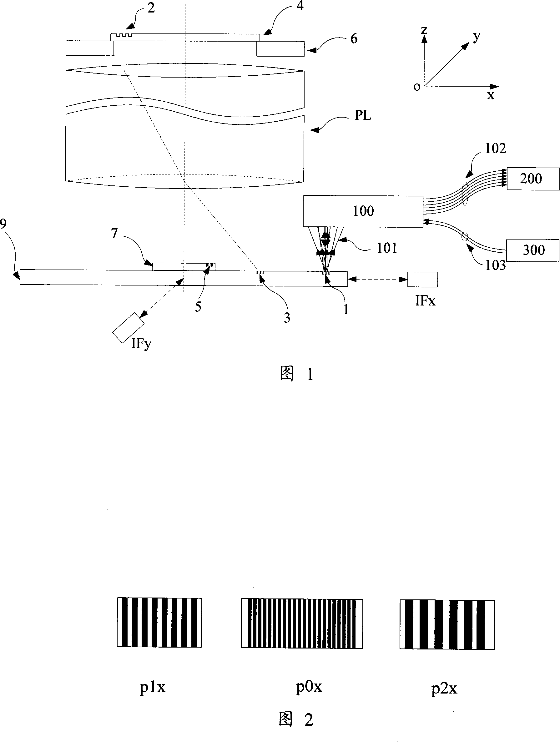
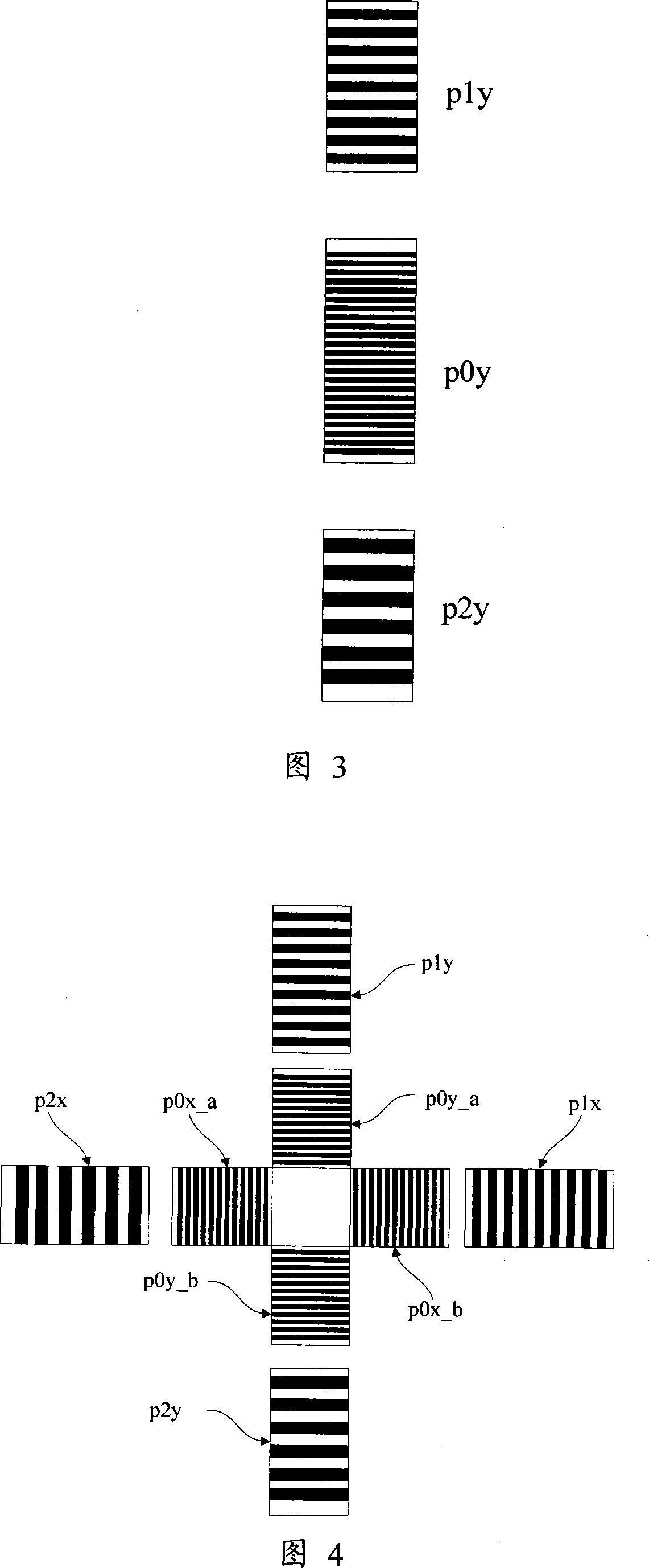
[0066] FIG. 1 shows an embodiment of an alignment method used in the prior art and an alignment method for a projection scanning lithography machine of the present invention, wherein the main structure of the lithography machine includes: a mask stage 6 , a mask Stencil 4 , projection objective PL, base stage 9 . Substrate table mark 1 and substrate mark 5 may be in the form of FIG. 2 , FIG. 3 or FIG. 4 . (Periodic relationship) The distribution of the substrate marks 5 on the substrate 7 may be in the form of FIG. 13 or FIG. 14 , wherein FIG. 13 is a combination of four groups of one-dimensional three-period marks.

[0067] In the alignment method used in the prior art, the reticle mark 2 on the reticle 4 carried by the reticle stage 6 is irradiated with a lower energy exposure radiation source or other non-exposure wavelength radiation sour...


PUM


Abstract

The invention discloses an alignment method of phase grating detection by using three basic grating periods applied in a scanning projection lithography tool and a micro-device manufacturing way by using the method. The alignment method of the invention applied in the scanning projection lithography tool uses three periods phase grating in a substrate marker or a substrate station reference marker, uses a first order diffraction light of the three periods as an alignment signal, simultaneously realizes a big capture range and gets high alignment precision and strong signal intensity, improves system signal to noise ratio, simplifies optical design and debugging difficulty, simplifies hardware realization, reduces signal processing cost and improves alignment efficiency.

Description

technical field [0001] The present invention relates to a lithography machine technology, in particular to an alignment technology of a scanning projection lithography machine. Background technique [0002] The application of a step-scan projection lithography machine to complete the pattern transfer task of micro-processing basically involves basic steps such as workpiece loading, workpiece to-be-processed area and reticle alignment, workpiece exposure and workpiece unloading, especially involving workpiece needs. In the case of multi-layer processing, the precise alignment of the workpiece to be processed area and the reticle is the premise to ensure that the workpiece is processed correctly under the condition that the line width is continuously reduced. When the graphics are accurately projected to the workpiece to be processed area or a new layer. When the graphic is accurately registered and projected on the to-be-processed area of ​​the previously formed workpiece, th...

Claims


Application Information

Patent Timeline
IPC IPC(8): G03F7/22G03F7/20G03F9/00H01L21/027
Inventor 韦学志李运锋徐荣伟周畅陈勇辉
Owner SHANGHAI MICRO ELECTRONICS EQUIP (GRP) CO LTD
Why Eureka
Try Eureka