Semi-conducting material thermoelectricity performance test system
A technology of thermoelectric performance and testing system, applied in the direction of single semiconductor device testing, semiconductor/solid-state device testing/measurement, material thermal development, etc., can solve the problems of inability to test Seebeck coefficient and electrical conductivity, etc., achieving convenient operation and wide application range , the effect of strong adaptability
- Summary
- Abstract
- Description
- Claims
- Application Information
AI Technical Summary
Problems solved by technology
Method used
Image

Examples
specific Embodiment approach 1
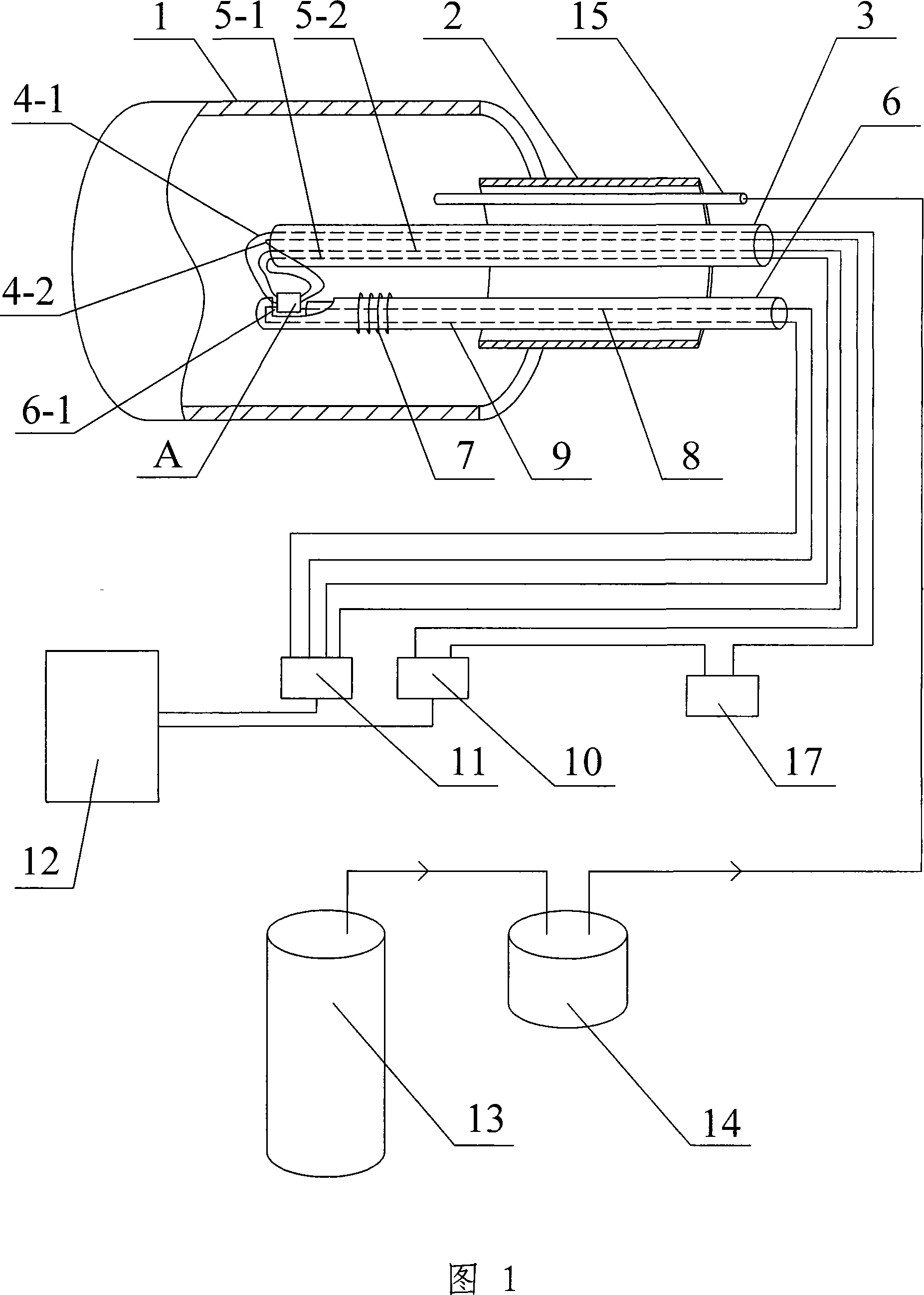
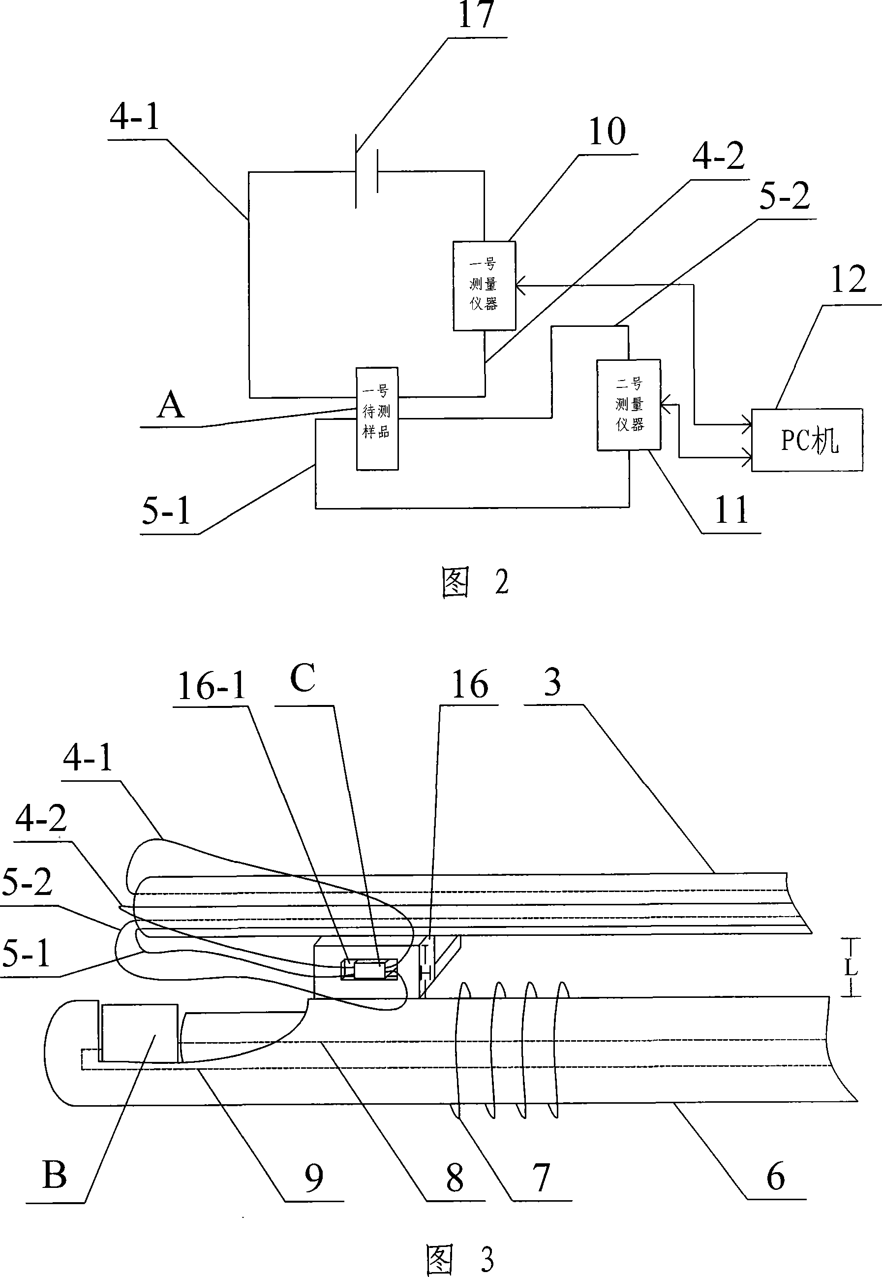
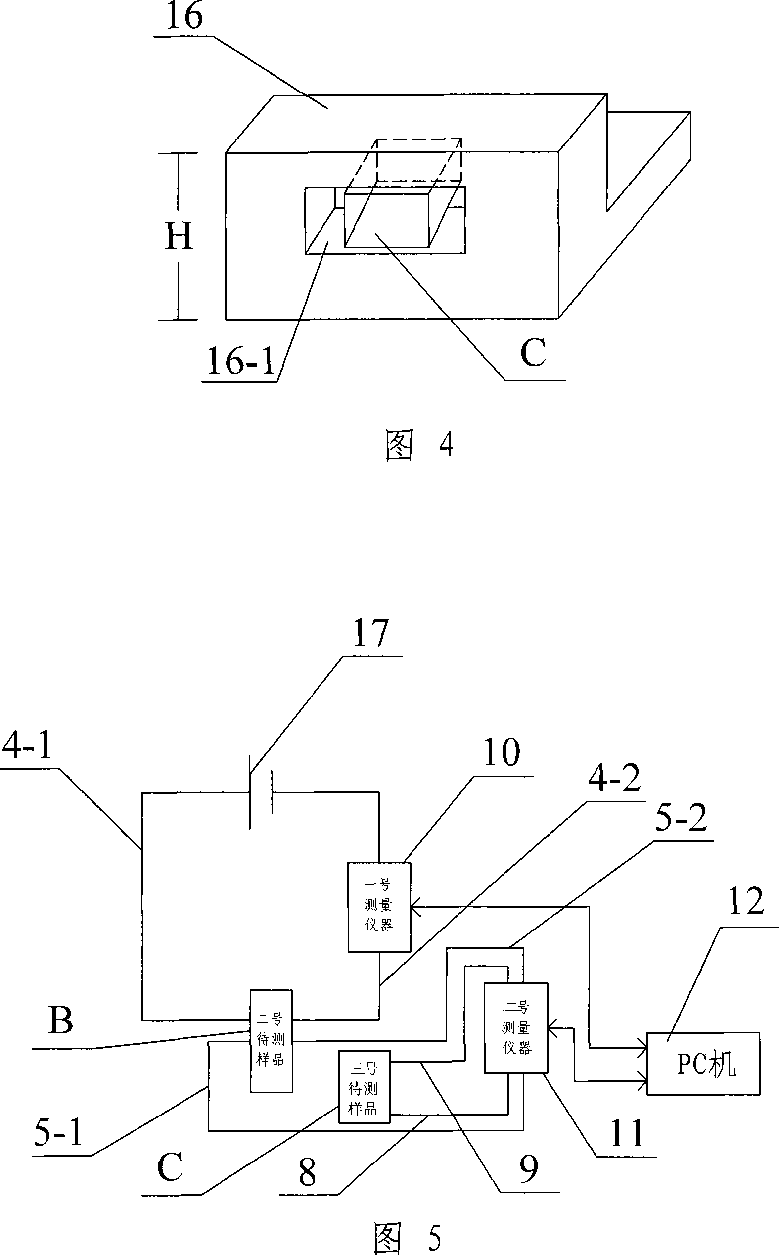
[0006] Specific embodiment 1: Referring to Fig. 1 and Fig. 2, this embodiment consists of a heating furnace 1, a connecting pipe 2, a No. 1 four-hole lead pipe 3, a positive current lead 4-1, a negative current lead 4-2, and a positive voltage lead 5 -1. Voltage negative lead wire 5-2, No. 2 four-hole lead tube 6, heating resistance wire 7, hot end thermocouple 8, cold end thermocouple 9, No. 1 measuring instrument 10 and No. 2 measuring instrument 11, connecting tube One end of 2 is connected to the heating furnace 1, the No. 1 four-hole lead tube 3 and the No. 2 four-hole lead tube 6 pass through the connecting tube 2 and extend into the heating furnace 1, the current positive lead 4-1, the current negative lead 4-2. Both the voltage positive lead wire 5-1 and the voltage negative lead wire 5-2 are set in the No. 1 four-hole lead tube 3, and the hot-end thermocouple 8 and the cold-end thermocouple 9 are set in the No. 2 four-hole lead tube 6 Inside, the No. 2 four-hole lead ...
specific Embodiment approach 2
[0007] Specific embodiment two: referring to Fig. 1, Fig. 2, present embodiment has increased PC machine 12 on the basis of specific embodiment one, the signal transmission end of No. 1 measuring instrument 10, the signal transmitting end of No. 2 measuring instrument 11 are respectively connected with The first signal transmission end of the PC 12 is connected to the second signal transmission end. According to the calculation formula of conductivity and Seebeck coefficient, the automatic measurement program is compiled and stored in PC 12, and the program is automatically recorded by PC 12, and the conductivity and Seebeck coefficient values are calculated according to the formula, and the obtained results can be intuitively displayed on the display of PC 12 superior. Other compositions and connections are the same as in the first embodiment.
specific Embodiment approach 3
[0008] Specific embodiment three: referring to Fig. 1, Fig. 2, present embodiment has increased protective atmosphere bottle 13, scrubber bottle 14 and air guide tube 15 on the basis of specific embodiment one, and air guide tube 15 is arranged in connecting pipe 2, guides The gas outlet of gas pipe 15 is communicated with heating furnace 1, and the gas inlet of air guide pipe 15 is connected with the gas outlet of gas washing bottle 14, and the gas inlet of gas washing bottle 14 is connected with the gas outlet of protective atmosphere bottle 13. The protective atmosphere in the protective atmosphere bottle 13 is filled into the heating furnace 1 through the gas washing bottle 14, which can prevent the high-temperature oxidation of the sample to be tested, and the filled protective atmosphere can be selected from argon. Other compositions and connections are the same as in the first embodiment.
PUM
 Abstract
Description
Claims
Application Information
 - Generate Ideas
- Intellectual Property
- Life Sciences
- Materials
- Tech Scout
- Unparalleled Data Quality
- Higher Quality Content
- 60% Fewer Hallucinations
Browse by: Latest US Patents, China's latest patents, Technical Efficacy Thesaurus, Application Domain, Technology Topic, Popular Technical Reports.
© 2025 PatSnap. All rights reserved.Legal|Privacy policy|Modern Slavery Act Transparency Statement|Sitemap|About US| Contact US: help@patsnap.com