
A novel CMOS oscillator circuit

A technology of oscillating circuits and oscillators, applied in the direction of power oscillators, electrical components, etc., can solve problems such as poor precision, high power consumption, and complicated circuits, and achieve the effects of simple structure, high precision, and reduced circuit cost and power consumption

Inactive Publication Date: 2008-02-20
BEIJING MXTRONICS CORP +1
View PDF0 Cites 7 Cited by
  • Summary
  • Abstract
  • Description
  • Claims
  • Application Information

AI Technical Summary

Problems solved by technology

The oscillator circuit is a circuit that generates a periodic output signal by relying on the self-excited oscillation of the circuit without an external input signal. Under the CMOS process conditions, the oscillator is generally an RC oscillator or a ring oscillator. The RC oscillator The structure is simple and easy to implement, but the accuracy is poor, and it varies greatly with temperature and power supply voltage. It is generally used in occasions that do not require high clock accuracy; in order to obtain better accuracy, the oscillator can use a ring structure, usually by Several delay circuits with a certain gain are formed in a closed-loop form, and the number of delay circuits is odd, but the disadvantage of the ring oscillator is that the circuit is more complicated, the power consumption is larger, and the temperature characteristics and power supply suppression ability are also poor.

Method used


Image

  • A novel CMOS oscillator circuit

Examples


Embodiment Construction

[0013] Below in conjunction with accompanying drawing and specific embodiment the present invention is described in further detail:

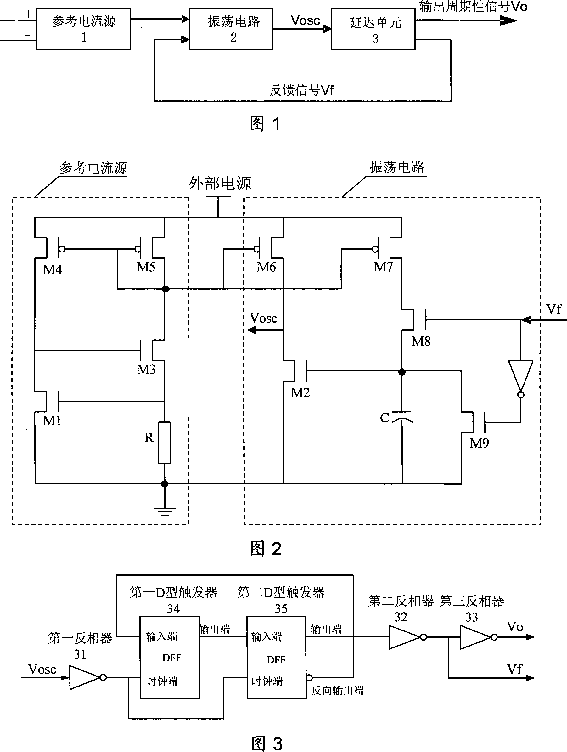
[0014] Figure 1 shows the basic form of a new type of CMOS oscillator circuit, including a reference current source 1, an oscillating circuit 2 and a delay unit 3, wherein the reference current source 1 uses a threshold voltage type current source to provide a bias current for the oscillating circuit 2, It can make the oscillator circuit work at more than ten milliampere currents, and the power consumption is very low. Oscillating circuit 2 generates an oscillating signal after receiving the bias current, and the oscillating signal outputs a periodic signal after being shaped by delay unit 3, and at the same time generates a feedback signal to oscillating circuit 2, and oscillating circuit 2 continues under the action of bias current and feedback signal The oscillator signal with stable frequency is output to realize the continuous and stable op...


PUM


Abstract

The utility model relates to a new CMOS oscillator circuit, comprising a reference current source, a oscillating circuit and a delay unit wherein, the reference current source provides offset current to the oscillating circuit; the oscillating circuit generates a oscillating signal after receiving the offset current. The oscillating signal is changed into periodic signal after shaping and delaying by the delay unit while generates a feedback signal to the oscillating circuit. The oscillating signal with stable frequency is continuously output by the oscillating circuit under the offset current and the feedback signal to realize the continuous stable operation of the CMOS oscillator. The utility model has advantages that the combined circuit structure of threshold voltage current source and oscillating circuit allows good temperature property and high power supply suppressing ability, low power consumption, and a substitute of the ceramics resonator, crystal and crystal oscillator module, and a clock source.

Description

technical field [0001] The invention relates to an oscillator circuit, in particular to a novel CMOS oscillator circuit. Background technique [0002] Oscillators are the main part of many electronic systems, and their applications range from clock generation in microprocessors to carrier synthesis in cellular phones. They can be widely used in measurement, remote control, communication, automatic control and other fields as clock sources. The oscillator circuit is a circuit that generates a periodic output signal by relying on the self-excited oscillation of the circuit without an external input signal. Under the CMOS process conditions, the oscillator is generally an RC oscillator or a ring oscillator. The RC oscillator The structure is simple and easy to implement, but the accuracy is poor, and it varies greatly with temperature and power supply voltage. It is generally used in occasions that do not require high clock accuracy; in order to obtain better accuracy, the osci...

Claims


Application Information

Patent Timeline
IPC IPC(8): H03B5/04
Inventor 王晋陆铁军赵宁康永华
Owner BEIJING MXTRONICS CORP
Learn More