Crewel vibrating silicon micro-gyroscopes

A silicon micro-gyroscope, line vibration technology, applied in the direction of speed measurement, instruments, generators/motors, etc. with gyro effect, can solve problems such as thermal stress and orthogonal coupling errors, large motion nonlinearity, and large gyroscope errors. , to achieve the effect of releasing thermal stress, reducing nonlinearity, and reducing error signals

Inactive Publication Date: 2008-03-05
NANJING UNIV OF SCI & TECH
View PDF0 Cites 8 Cited by
  • Summary
  • Abstract
  • Description
  • Claims
  • Application Information

AI Technical Summary

Problems solved by technology

Although this structure overcomes the shortcomings of the motion coupling of the above-mentioned structure, the motion nonlinearity is relatively large, so the motion range is limited, and the thermal stress and orthogonal coupling errors are relatively large.
Therefore, the gyroscope has large error, poor stability and low sensitivity

Method used


Image

  • Crewel vibrating silicon micro-gyroscopes
  • Crewel vibrating silicon micro-gyroscopes
  • Crewel vibrating silicon micro-gyroscopes

Examples


Embodiment Construction

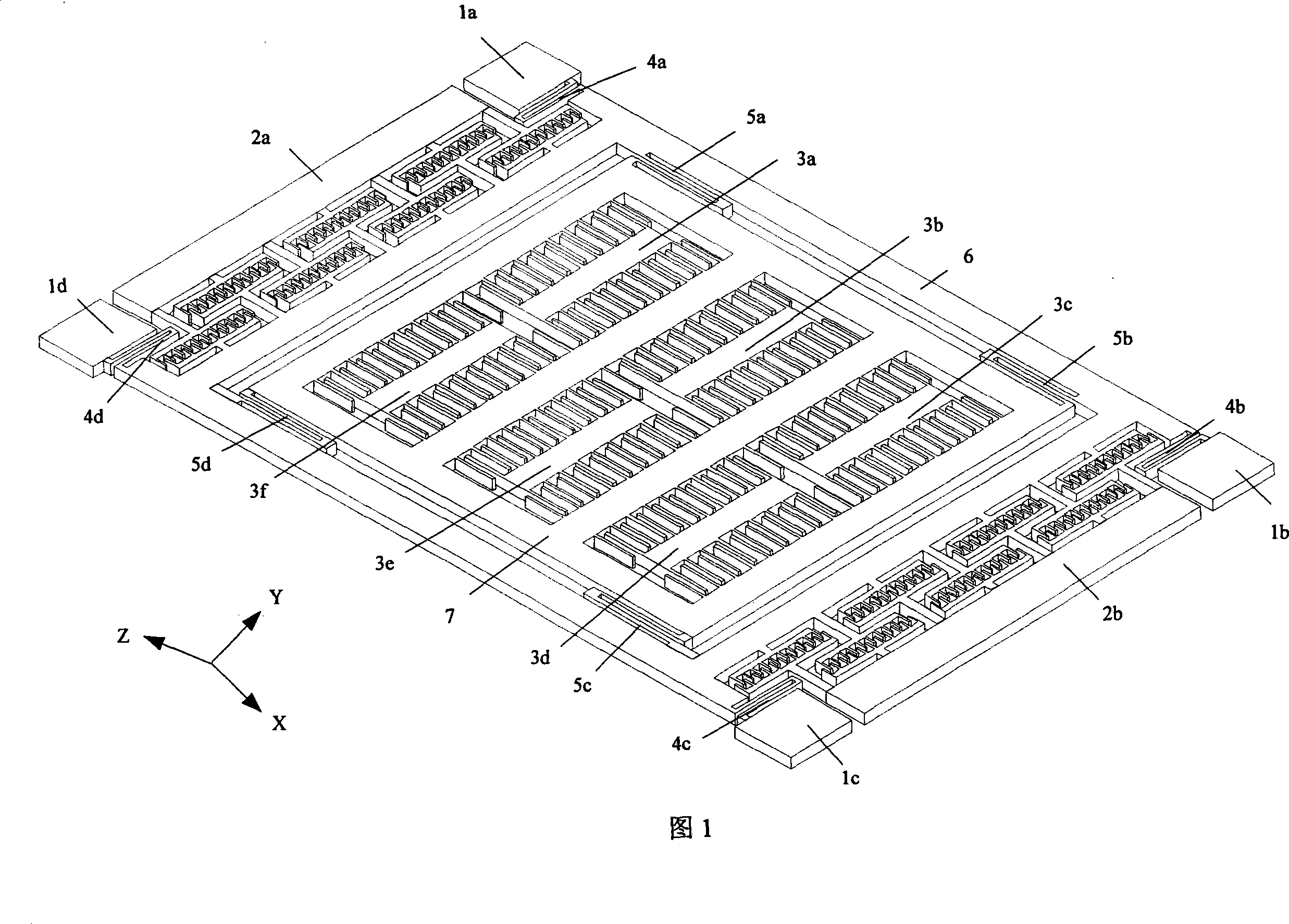
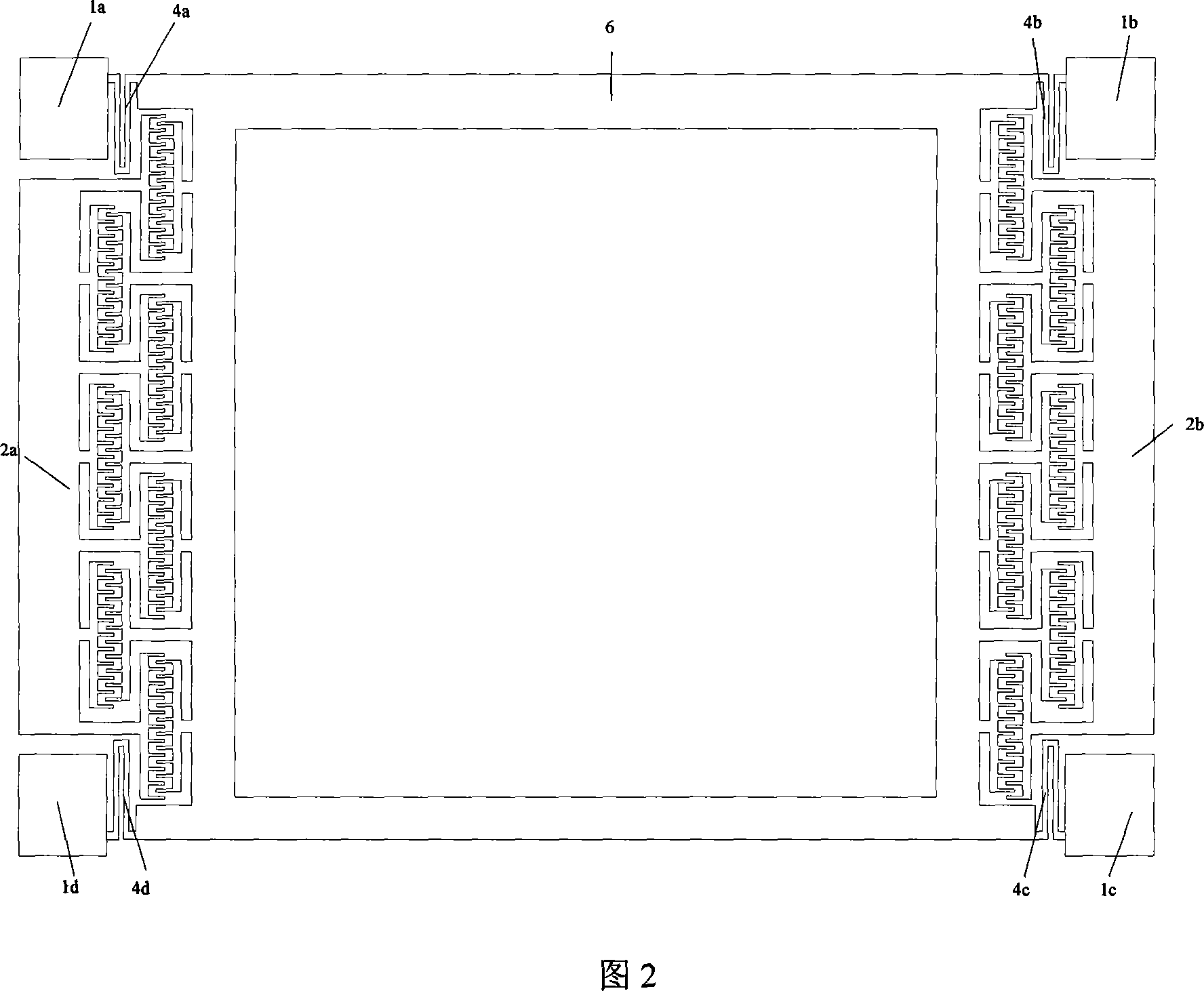
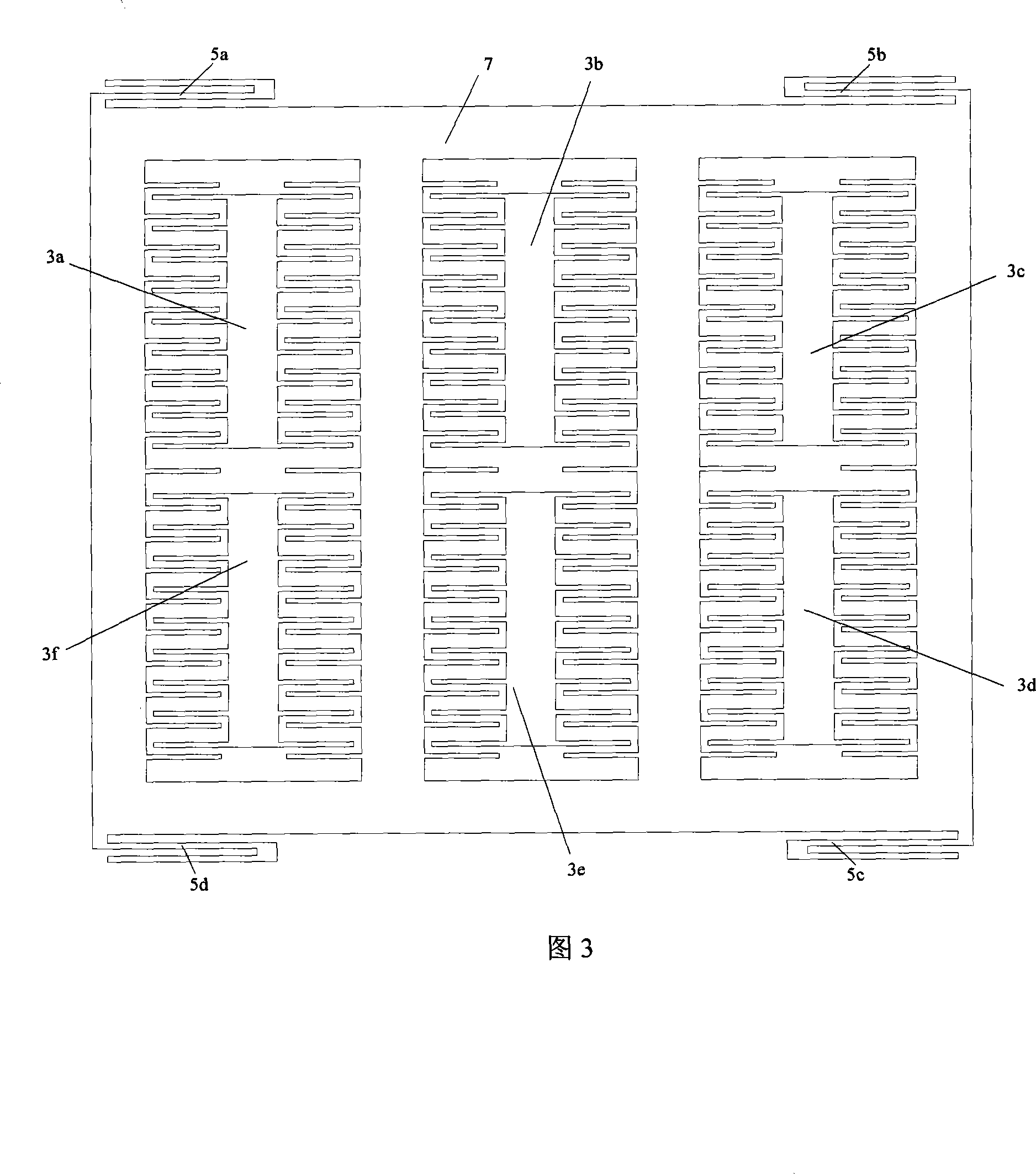
[0017] In conjunction with Fig. 1 and Fig. 4, the double-wire vibrating silicon micro-gyroscope of the present invention is used to measure the measuring instrument perpendicular to the base level, and consists of upper and lower layers, and the upper layer is a gyroscope machine made on a single crystal silicon wafer. Structure, the lower layer is the signal leads made on the glass substrate, the inner frame 7 of the upper mechanical structure of the gyroscope is connected with the outer frame 6 through the detection support beams 5a, 5b, 5c, 5d, and the lower layer of the gyroscope is made on the glass substrate. Line 8, drive input leads 9a, 9b, sensitive output signal leads 10a, 10b, the upper mechanical structure is installed on the glass substrate through the fixed bases 1a, 1b, 1c, 1d corresponding to the fixed base bonding points 11a, 11b, 11c , 11d, the upper mechanical structure part is suspended above the lower glass substrate part, and the driving support beams 4a, ...


PUM


Abstract

The invention comprises an upper layer and a lower layer. On the upper layer there is a gyroscope mechanical structure made on a monocrystalline silicon plate; on the lower layer there are signal leads made on the glass substrate. The inner frame of the gyroscope upper layer mechanism structure is connected to the outer frame of the detection support beam; on the gyroscope lower layer glass substrate there are grounding lines, driving input leads, sensitive output signal lines; the upper layer mechanical structure is mounted on the linkage point of the fixed base on the glass substrate through the fixed base in order to make the upper layer mechanical structure hang above the lower layer glass substrate. The invention features U-shaped beam structure used by both the driving sport beam and detection support beam.

Description

technical field [0001] The invention belongs to micro-electromechanical system and micro-inertia measurement technology, in particular to a two-line vibrating silicon micro-gyroscope. Background technique [0002] Micromachined inertial instruments include micromachined gyroscopes (MMG) and micromachined accelerometers (MMA). The use of microelectronic processing technology allows the complete integration of micromechanical structures and required electronic circuits on a silicon chip, thereby achieving a high degree of unity in terms of performance, price, volume, weight, and reliability. Therefore, this type of instrument has a series of advantages (such as small size, light weight, cheap price, high reliability, mass production, etc.), and has broad application prospects in both military and civilian fields. In civilian use, it is mainly used in the automotive industry, industrial monitoring and consumer products and robotics, such as airbags, anti-lock braking systems, ...

Claims


Application Information

Patent Timeline
Patent Type & Authority Applications(China)
IPC IPC(8): G01C19/56B81B7/02G01P9/04G01P15/097G01C21/18
Inventor 苏岩裘安萍施芹朱欣华
Owner NANJING UNIV OF SCI & TECH
Why Eureka
Try Eureka