Diffraction color changing laser marking method and apparatus thereof

A laser marking method and laser marking technology are applied in the field of diffractive color-changing laser marking and devices, which can solve the problems of low image resolution, low absorption rate, difficulty in focusing, etc., so as to improve the resolution and reduce the etching depth. , The effect of uniform light intensity distribution

Active Publication Date: 2008-03-05
SVG TECH GRP CO LTD +1
View PDF0 Cites 16 Cited by
  • Summary
  • Abstract
  • Description
  • Claims
  • Application Information

AI Technical Summary

Problems solved by technology

However, it has the following problems: (1) In order to obtain the laser output of high average power, the laser beam of the marking machine is a multi-transverse mode spot (M 2 <10), the smallest light spot can be focused to about 50 μm, and for a thinner beam, it is difficult to focus; (2) During laser marking, the focused beam forms a high-energy-density light spot that generates high temperature locally to ablate the material. The wavelengths used in the laser marking system are 1060nm and 532nm. Generally, the material to

Method used


Image

  • Diffraction color changing laser marking method and apparatus thereof
  • Diffraction color changing laser marking method and apparatus thereof
  • Diffraction color changing laser marking method and apparatus thereof

Examples


Embodiment 1

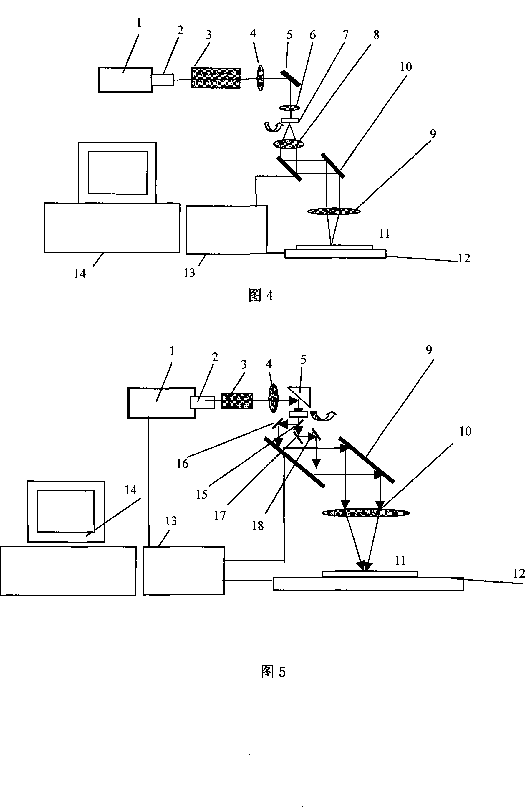
[0055] Embodiment 1: Refer to Figure 4, a method for making color-changing grating images. The image distribution is converted into pulse control signals. According to the orientation of the unit grating and the space frequency, the interference optical head, platform movement, grating rotation and light are simultaneously performed. Pulse input, etching on the surface of the material.

[0056] It consists of laser light source 1, beam expander 2, spot shaper 3, variable rectangular aperture imaging system 4, 5, 6 (lens 4, 6 and diaphragm constitute a 4F system with microfilm function), beam splitting system (including beam splitting Component quartz phase grating and turntable 7, imaging lens group 8, F-theta lens 9), the above-mentioned interference type optical head composed of light source, beam shaping, and beam splitting system, insert a 2-dimensional galvanometer between the imaging lens groups 8, 9 10. The material 11 is placed on the two-dimensional work platform 12 and t...

Embodiment 2

[0060] Embodiment 2: As shown in Figure 5, a laser etching and marking system is realized, including a DPSSL laser light source with a TTL signal interface 1, a beam expander collimator 2, an iris and a shaper 3, The quartz lens 4 (objective lens), the mirror 5 and the F-theta lens 9 together form a 4F system, which forms a reduced image on the surface of the recording material 11 for the rectangular diaphragm. Since the position of the beam splitting element has nothing to do with the shape of the final light spot, the beam splitting element should be as close as possible to the lens 4 to make the beam on the transflective beam splitter 14 larger. After the beam is split, it is reflected by the mirrors 15, 16, 17, and the parallel light after the split beam is condensed on the material 11 through the imaging lens group 10.

[0061] The above-mentioned interference optical head composed of laser light source, beam splitting element and imaging system, material 11 is placed on the ...

Embodiment 3

[0063] Embodiment 3: On the basis of Embodiment 1, the iris is opened to the minimum, the beam splitting element is rotated to a blank place, the laser beam does not split light, and directly penetrates the imaging lens group to adjust the light spot focused on the material To 2-50 microns, increase the repetition frequency of the pulsed laser beam, the marking system can directly write two-dimensional vector graphics, the system becomes a single-beam precision laser direct writing system, which can perform photoetching of precision circuit boards and reticles . The overall structure of the etching system of this embodiment is the same as that of the first embodiment, and the lens 9 adopts a shorter focal length (microscopic objective lens with high numerical aperture).


PUM

PropertyMeasurementUnit
Etching depthaaaaaaaaaa
Angleaaaaaaaaaa
Pulse widthaaaaaaaaaa

Abstract

The method thereof comprises: using a high power semiconductor pumping solid state laser as light source; the laser beam satisfies the requirement of interference; using a beam-splitting component to generate a beam-splitting light; using a optical lens group to converge the light spot on the material surface to form an even interference fringe optical field; the laser power density on the surface of the materials is over a damage threshold to form the fringe etch; by controlling the scan, realizing the marking of diffracted light color-changed image.

Description

Technical field [0001] The invention relates to a device designed based on a printing or marking process, in particular to a marking method and device with diffractive discoloration characteristics realized by a laser system. Background technique [0002] Laser marking uses a high-energy-density laser beam to act on the target to cause physical or chemical changes on the target surface to obtain a visible pattern marking method. The laser marking system can form text, graphics, product serial numbers, etc. on the surface of the material. The high-energy laser beam is focused on the surface of the material to quickly vaporize the material and form pits. As the laser beam moves regularly on the surface of the material while controlling the laser's interruption, the laser beam will be processed on the surface of the material to form a specified pattern . Laser marking is a non-contact processing method. It is popular for its fast marking speed, no wear, easy operation, and easy to r...

Claims


Application Information

Patent Timeline
IPC IPC(8): G02B26/10G02B27/10G02B5/18H01S5/00B41J2/47
Inventor 解正东陈林森浦东林魏国军周小红张恒周云
Owner SVG TECH GRP CO LTD
Why Eureka
Try Eureka