Luminescent multilayer system and utilisation thereof

A technology of objects and light-emitting layers, which is applied in the application field of light-emitting objects in optical light-emitting concentrator devices, and can solve problems such as low-efficiency coupling, low-efficiency maintenance of light, and low total efficiency

Inactive Publication Date: 2008-03-05
SIGNIFY HLDG BV
View PDF7 Cites 16 Cited by
  • Summary
  • Abstract
  • Description
  • Claims
  • Application Information

AI Technical Summary

Problems solved by technology

At this time, the LSC system is not yet commercially available, which is mainly related to its low efficiency
This low overall efficiency stems from the high reabsorption of emitted light (limited Stokes shift of the dye), inefficient coupling of light into the waveguide, and inefficient keeping of light within the waveguide

Method used


Image

  • Luminescent multilayer system and utilisation thereof
  • Luminescent multilayer system and utilisation thereof
  • Luminescent multilayer system and utilisation thereof

Examples


Embodiment 1

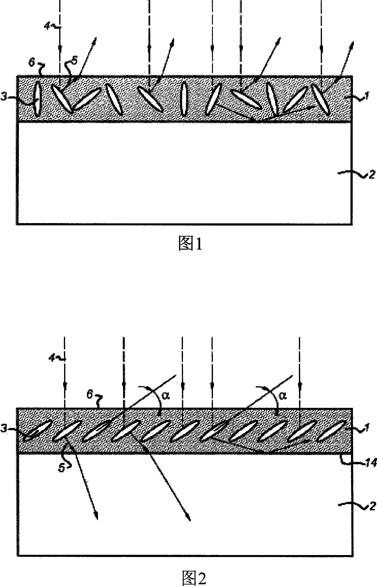
[0162] Applications of Vertically Aligned Photoluminescent Polymer Coatings

[0163] A vertical dye-doped liquid crystal mixture was applied to a clean 30 mm x 30 mm x 1 mm glass slide. The liquid crystal mixture can be obtained by mixing 1% by weight of Irgacure 184 (ex CibaChemicals) and 1% by weight of Coumarin 30 (ex Aldrich Chemicals) with a solution containing The percentage is 50% of RMM77 monomer and 50% by weight of xylene, and the weight ratio of RMM77 monomer to xylene is 1:1. RMM77 (Merck) is a nematic vertical active liquid crystal, and its main components are liquid crystals RM82 and RM257 (both Merck) and vertical dopants. The mixture was stirred at 80°C for 2 hours until all the ethanol had evaporated. Xylene can be evaporated by placing the mixture on a preheated waveguide (80° C.) for 10 minutes. After evaporating the xylene, wet films were prepared using a 24 um Meyer rod to produce a film about 10 um thick. The sample is at room temperature, under N 2 ...

Embodiment 2

[0170] A clean glass substrate (Optimer A1 1051, ex JSR Micro) with a polyimide alignment layer, and the polyimide alignment layer is 2500 rpm / s at a speed of 2000 rpm / s 2 Spin-coating of accelerations for 45 s was obtained. The substrate was then heated at 180° C. in vacuum for 1.5 hours. The alignment layer was rubbed with a velvet cloth to bring about planar alignment of the cholesteric liquid crystals used. The vertical dye described in Example 1 was then doped into the liquid crystal mixture (this time using the dye DCM(4-(dicyanomethylene)-2-methyl-6-(4-dimethylaminostyryl)-4H -pyran) (ex Aldrich Chemicals)) was applied to the opposite side of the substrate.

[0171] The mixture was prepared by mixing 1% by weight of Irgacure 184 (ex Ciba Chemicals) and 1% by weight of Dipentaerythritol Pentaacrylate (Aldrich) at 75% by weight and 25% by weight of % ethanol solution mixed. A thin film approximately 10 m thick can be formed by spin coating at 4000 rpm for 45 seconds (...

Embodiment 3

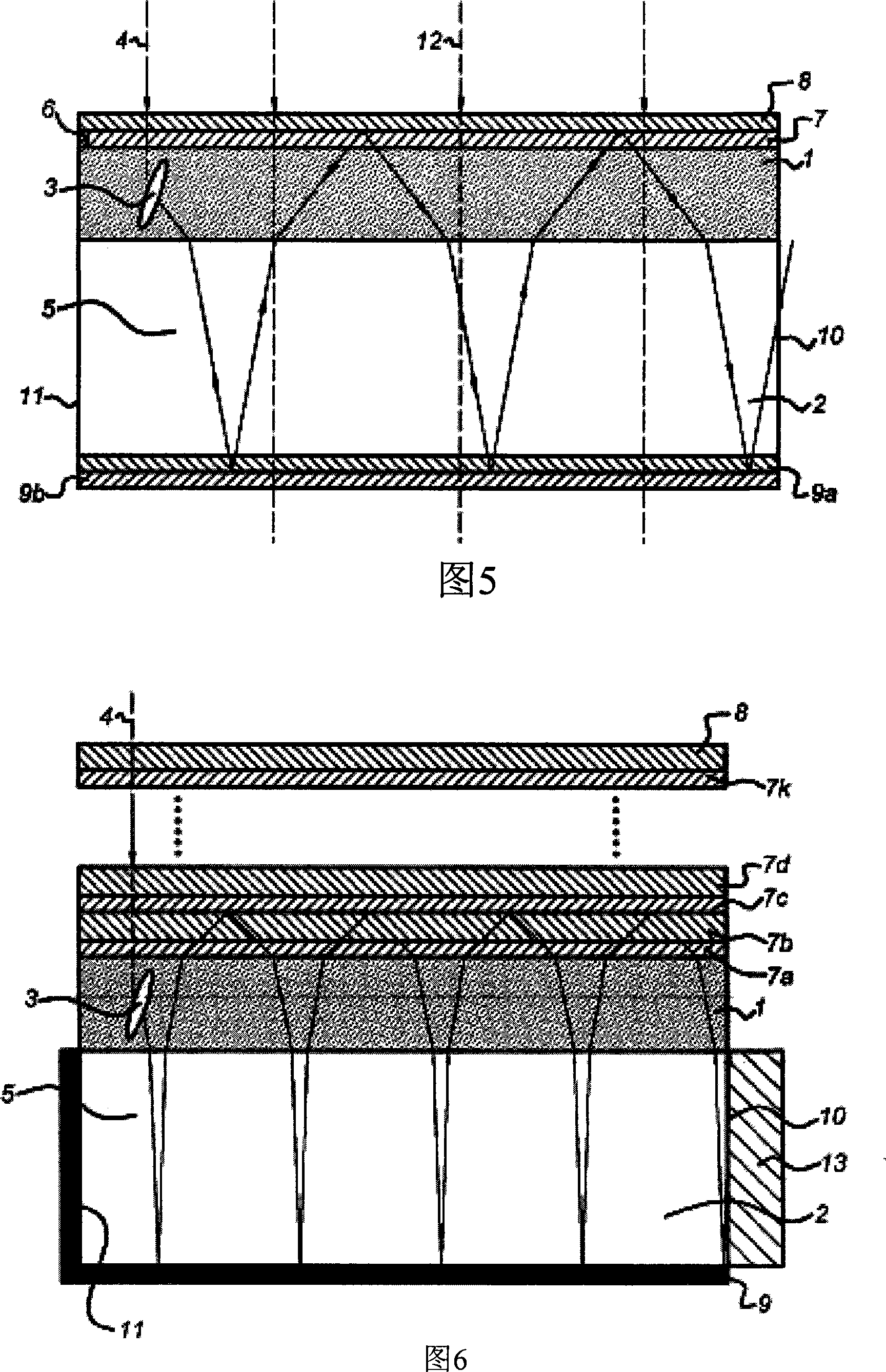
[0188] Example 1 was repeated except that a liquid crystal polymer was used, and the liquid crystal polymer was obtained by using the process described in Sinha et al in Appl. Phys. Lett. (2001), 79(16), 2543-2545, along Arranged at an inclination angle of about 30°.

[0189] The efficiency of the LSC was measured again using the method described in Example 1. The results show that the efficiency of this LSC exceeds that of the LSCs described in Examples 1 and 2. This excellent efficiency is believed to be related to the enhanced coupling of the emitted radiation into the waveguide.


PUM


Abstract

A first aspect of the invention relates to a luminescent object comprising: a. a luminescent layer or core containing a photoluminescent material; and b. a wavelength-selective mirror; wherein the luminescent layer or luminescent core is optically coupled to the wavelength-selective mirror, said wavelength-selective mirror being at least 50% transparent to light absorbed by the photoluminescent material and at least 50% reflective to radiation that is emitted by the photoluminescent material. The luminescent object according to the present invention may advantageously be employed in luminescent solar concentrator systems as it enables highly efficient transportation of radiation emitted by the photoluminescent material fo llowing exposure to incident solar light. Another aspect of the invention concerns a photovoltaic device comprising an electromagnetic radiation collection medium containing the aforementioned luminescent object and a photovoltaic cell capable of converting optical radiation to electrical energy which is optically coupled to the luminescent object. Further aspects of the invention include a fluorescent light activated display and a room lighting system comprising the aforementioned luminescent object.

Description

technical field [0001] The present invention relates to a luminous object, in particular to the application of such a luminous object in an optical luminescent concentrator device (eg a luminescent solar concentrator device). Background technique [0002] The cost per watt of solar energy is approximately 5-10 times higher than energy from other sources including coal, oil, wind, biological and nuclear. In order to reduce the cost of solar power generation in photovoltaic systems, it is desirable to efficiently utilize the most expensive part of the system, the photovoltaic cell (solar cell). This is usually achieved through the use of large light-focusing solar concentrators (parabolic or trough-shaped disks). These devices suffer from a number of disadvantages including high capital cost, high maintenance cost, bulky form factor and the need to track the sun as it passes across the sky: for a review of the state of the art see Swanson, Progress in Photovoltaics: Research ...

Claims


Application Information

Patent Timeline
Patent Type & Authority Applications(China)
IPC IPC(8): H01L31/055F24J2/06F24S23/00
CPCY02E10/52Y02E10/44H01L31/055
Inventor 迈克尔·G·戴比杰希斯·W·M·巴斯提安森迪克·J·布罗尔迈克尔·J·艾斯古奇卡罗斯·桑切
Owner SIGNIFY HLDG BV
Why Eureka
Try Eureka