Micro-heat current gyroscopes

A gyroscope and micro-heating technology, applied in the field of sensors, can solve the problems of jet deflection, gyroscope processing complexity, and the inability to achieve the optimum at the same time, and achieve the effects of overall size reduction, high convective heat transfer efficiency, and large-scale production

Inactive Publication Date: 2008-03-12
刘胜
View PDF2 Cites 14 Cited by
  • Summary
  • Abstract
  • Description
  • Claims
  • Application Information

AI Technical Summary

Problems solved by technology

This gyroscope has a disadvantage: in the case of non-uniform angular velocity, both the Gothic force and the tangential force caused by angular acceleration will cause the jet to deflect, so the temperature difference between the thermal sensors contains both angular velocity and angula

Method used


Image

  • Micro-heat current gyroscopes
  • Micro-heat current gyroscopes

Examples


Embodiment Construction

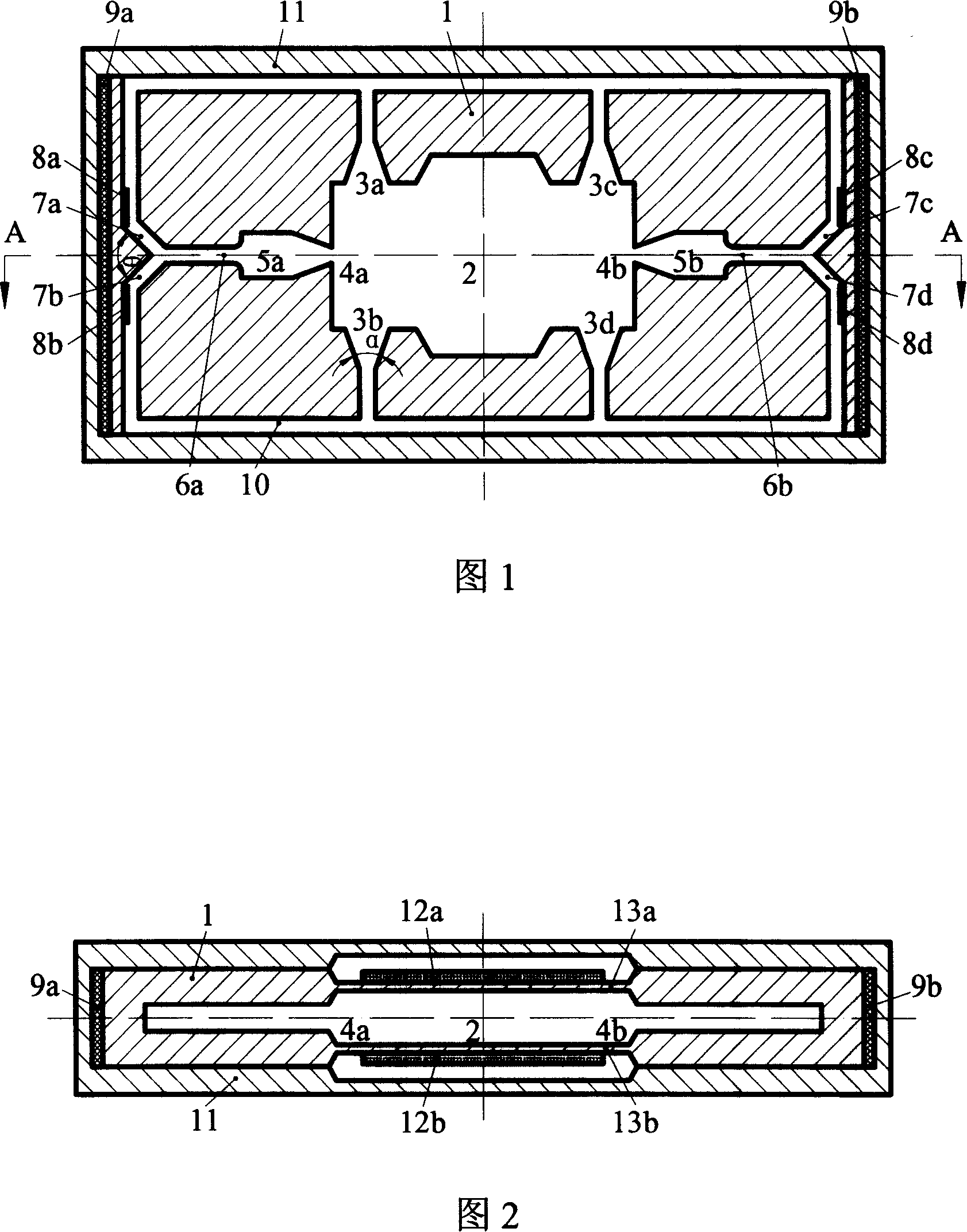
[0019] Embodiments of the present invention are further described below in conjunction with the accompanying drawings:

[0020] Referring to Fig. 1 and Fig. 2, a cavity 2, a first tapered shrink tube 3a, a second tapered shrink tube 3b, a third tapered shrink tube 3c, a fourth tapered shrink tube 3d, and a fourth tapered shrink tube 3d are opened on the base body 1. A tapered diffuser tube 4a, a second tapered diffuser tube 4b, a first buffer chamber 5a, a second buffer chamber 5b, a first main microfluidic channel 6a, a second main microfluidic channel 6b, a first shunt channel 7a, a second Two shunt passages 7b, a third shunt passage 7c, a fourth shunt passage 7d, and a return pipe 10. The cavity 2 is located at the center of the base body 1. The first tapered shrink tube 3a and the second tapered shrink tube 3b pass through the cavity 2, The first tapered diffusion tube 4a, the first buffer chamber 5a, and the first main microfluidic channel 6a are respectively connected wi...


PUM


Abstract

The invention relates to a micro heat flow gyroscope, adopting the two-way fluid shunt channel structure, which generates two fluids with the completely same speed and temperature and the opposite speed direction through the periodic alternative change of volume of a driving membrane vibration deformation control chamber; the fluids respectively flow through their own cushion chamber and main micro-flow channel, shunt to the symmetrically arranged shunt channel with a thermosensitive device, the convective heat transfer between the thermosensitive device and the fluid comprises angular velocity information, and the angular velocity is gained through detecting the temperature difference of two pairs of symmetrically arranged thermosensitive devices. The invention has the advantages of effectively reducing the negative influence of centrifugal force coupling on detection precision, simultaneously optimizing the detection precision and range, being applied to the occasion of uniform angular velocity and non-uniform angular velocity, and having the simple structure and the high sensitivity and resolution.

Description

technical field [0001] The invention relates to a sensor, in particular to a micro heat flow gyroscope for detecting angular velocity. technical background [0002] Gyroscopes have been widely used in various fields, such as missile inertial guidance in the military, motion monitoring of automobiles or robots in industry, and various consumer electronics products. The great demand for small-size, low-cost, high-performance and high-reliability micromachined gyroscopes will promote the industrialization of such products. The micromechanical gyroscopes that have been developed so far have relatively complicated processing technology, and their principles are generally based on capacitance and piezoelectric effects, resulting in complex circuits and high costs. [0003] US Patent 5012676 proposes a gas gyroscope. It takes the pump as the core working part, and detects the angular velocity based on the difference between the convective heat transfer between the jet flow under ...

Claims


Application Information

Patent Timeline
IPC IPC(8): G01C19/56G01P9/04
Inventor 刘胜艾叶罗小兵
Owner 刘胜
Why Eureka
Try Eureka