

Sperm analyse
A semen, sperm technology, applied in the field of semen analysis, can solve the problem of excess light absorption rate measurement and other problems
- Summary
- Abstract
- Description
- Claims
- Application Information
AI Technical Summary
Problems solved by technology
Method used
Image

Examples
example 1
[0088] As mentioned above, compared with animal samples, the automated optical measurement of TSC in human semen samples has been restricted in the past due to the lower concentration of sperm cells. This, together with the high electronic and optical background noise caused by, for example, the variability of the semen slurry, prevents the application of methods routinely used in veterinary student fertility analysis. The method of the present invention overcomes these obstacles by combining the following features:
[0089] (i) Place the sample in a transparent container between the synchronized pulsed light source and the synchronized activated photodetector. The use of a synchronized pulsed light source and a photodetector makes it possible to identify sperm cells at low concentrations at the level of electronic noise.
[0090] (ii) Measure the light absorption of the sample in the 800-1000nm range. It has been found that measuring absorbance in the near-infrared region provide...
example 2
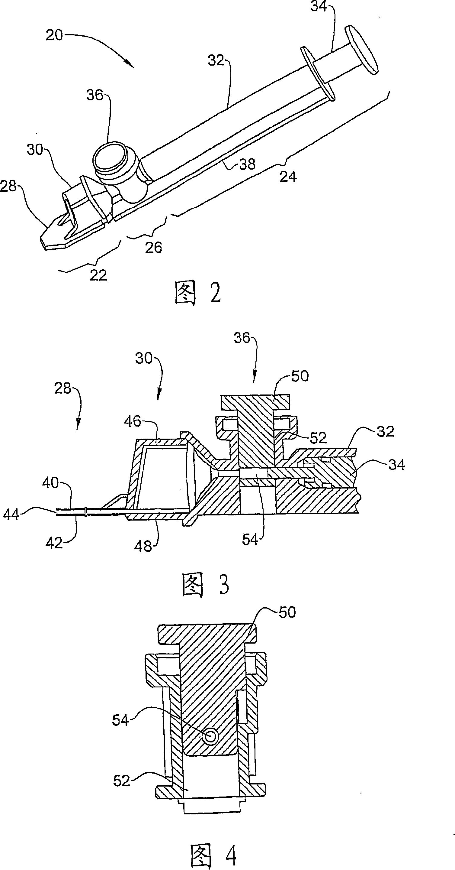
[0096] Figure 2 shows an embodiment of a sampling device 20 according to the invention for use in measuring semen. The device includes an optical observation part 22 at the front, a suction part 24 at the rear, and an air discharge part 26 in the middle.
[0097] The optical observation section 22 includes a fine measurement chamber 28 and a coarse measurement chamber 30. The fine measurement chamber is used for measuring MSC and / or for visual inspection, and the coarse measurement chamber is used for measuring TSC. In this way, multiple parameters can be measured simultaneously using the same sampling equipment and sampling steps.
[0098] The suction part 24 includes a suction cylinder 32 and a plunger 34 slidably inserted therein. These components cooperate with each other and work as in a standard syringe. This part is used to suck the semen sample into the measurement chamber.
[0099] The air discharge part 26 includes a partition valve 36 for separating the measurement cham...
example 3
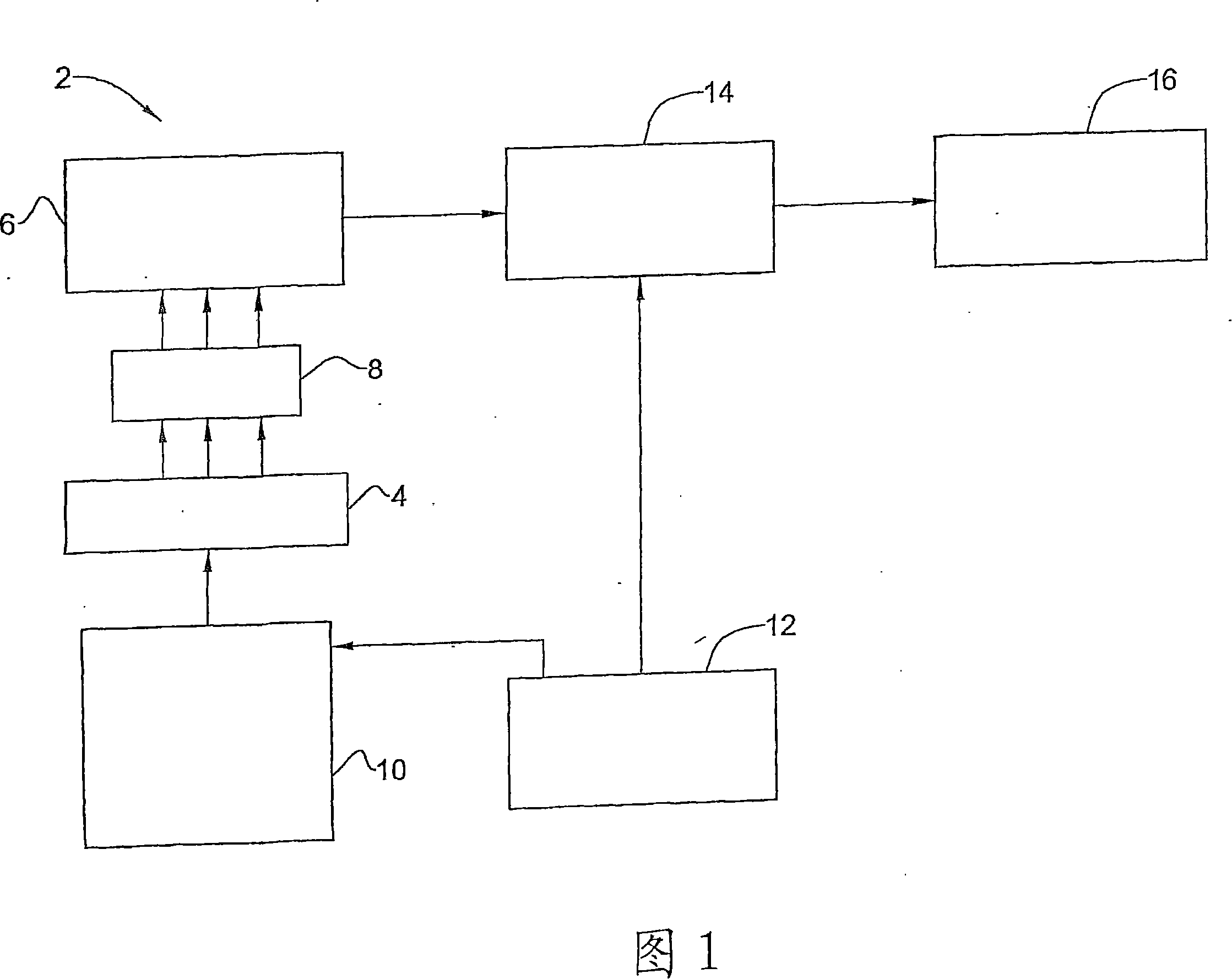
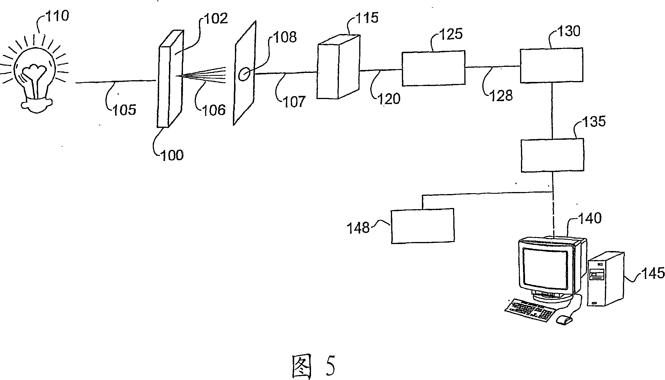
[0111] As described above, the determination of the MSC according to the present invention requires generating a voltage signal proportional to the MSC. Figure 5 shows an embodiment of a system for semen analysis that can generate such a signal.
[0112] The optical capillary 100 having a rectangular cross-section is used to hold the semen sample 102. The capillary 100 is illuminated by the incident light beam 105 generated by the light source 110. The capillary 100 has an optical path of 300 μm through which the light beam 105 passes. After passing through the capillary, the scattered beam 106 is collimated by a circular hole 108 with a diameter of 70 μm. The collimated light beam 107 irradiates the photodetector 115. The photodetector 115 generates an analog voltage signal 120 proportional to the intensity of the light beam 107. Due to the movement of the sperm in the semen sample 102, the analog signal changes with time, as illustrated in FIG. 8 by way of example. The analog si...
PUM
| Property | Measurement | Unit |
|---|---|---|
| Size | aaaaa | aaaaa |
Abstract
Description
Claims
Application Information