Self-respiration type fuel battery membrane electrode and method for producing the same

A fuel cell membrane and self-breathing technology, which is applied in the direction of fuel cells, battery electrodes, fuel cell components, etc., can solve the problems of membrane electrode influence, high contact resistance, and affecting the performance of membrane electrode work, so as to improve performance , The effect of resistance reduction

Inactive Publication Date: 2008-04-09
HARBIN INST OF TECH
View PDF2 Cites 25 Cited by
  • Summary
  • Abstract
  • Description
  • Claims
  • Application Information

AI Technical Summary

Problems solved by technology

[0003] In order to solve the problem that the current collecting method of the existing membrane electrode has large contact resistance, it is not conducive to the integration of the electric stack, especially the self-breathing fuel cell; CN1591940A removes the cathode diffusion layer, so that the membrane electrode lacks the cathode air filter protection layer, For the problem that the membrane electrode is easily affected by the outside world and affects the performance of the membrane electrode for a long time, a self-breathing fuel cell membrane electrode and its preparation method are provided. The specific technical solution to solve the above problems is as follows:

Method used


Image

  • Self-respiration type fuel battery membrane electrode and method for producing the same

Examples


specific Embodiment approach 1

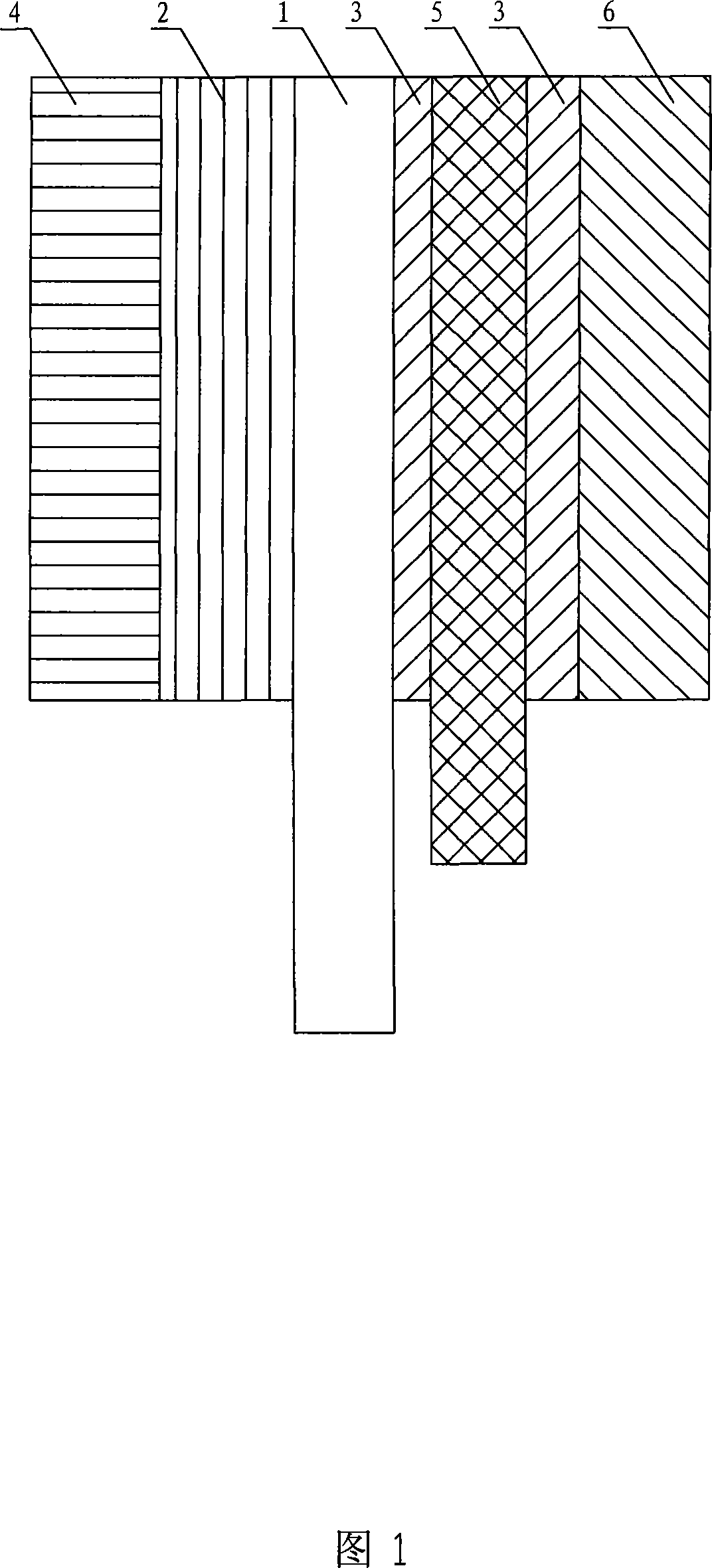
[0023] Specific implementation manner 1: This implementation manner is described in conjunction with FIG. 1 . This embodiment consists of a proton exchange membrane 1, an anode catalyst layer 2, a cathode catalyst layer 3, an anode diffusion layer 4, a porous metal mesh current collector 5, and a cathode diffusion layer 6. The porous metal mesh collector 5 is vertically arranged on the cathode catalyst Inside the layer 3, the anode catalytic layer 2 is arranged on the left side of the proton exchange membrane 1, the cathode catalytic layer 3 is arranged on the right side of the proton exchange membrane 1, the left side of the anode catalytic layer 2 is provided with an anode diffusion layer 4, and the cathode catalytic layer The right side of 3 is provided with cathode diffusion layer 6, proton exchange membrane 1, anode catalyst layer 2, cathode catalyst layer 3, anode diffusion layer 4, porous metal mesh current collector 5 and cathode diffusion layer 6 are hot-pressed and so...

specific Embodiment approach 2

[0026] Embodiment 2: The lead wire in this embodiment is connected to the protruding end of the porous network current collector 5 . Draw the current out.

specific Embodiment approach 3

[0027] Embodiment 3: The anode diffusion layer 4 and the cathode diffusion layer 6 of this embodiment are coated with polymer slurry on carbon paper or carbon cloth (the carbon paper or carbon cloth is produced by Toray Corporation of Japan).


PUM


Abstract

The invention discloses a membrane electrode of air-breathing fuel cells and a fabrication method thereof, relating to the membrane electrodes of air-breathing fuel cells and the fabrication method. The invention resolves the problem that the contact resistance of the electron current collection mode of the prior film electrode is large, which is harmful to electric pile integration. In the membrane electrode in the invention, a porous metal reticular current collector (5) is longitudinally provided inside a cathode catalyst layer (3), and a proton exchange membrane (1), an anode catalyst layer (2), the cathode catalyst layer (3), an anode diffusion layer (4), the porous metal reticular current collector (5) and a cathode diffusion layer (6) are solidified by hot pressing into a unity. The fabrication method includes that: 1. fabricating the anode diffusion layer; 2. fabricating the cathode diffusion layer; 3. integrating the porous metal reticular current collector with the cathode catalyst layer; 4. fabricating the anode catalyst layer; 5. fabricating the cathode catalyst layer; 6. the membrane electrode is formed by hot pressing. The invention uses the internal current collection mode, allowing the air-breathing fuel cells to reduce the resistance of membrane electrodes and enhancing the performance of membrane electrodes.

Description

technical field [0001] The invention relates to fuel cell technology, in particular to a membrane electrode of a self-breathing fuel cell. Background technique [0002] In recent years, with the rapid development of portable electronic products, all kinds of batteries currently on the market are secondary batteries, which must be recharged before they can be reused. The service life is short, and there are potential safety hazards and disposal problems for batteries. Therefore, it has become a research focus to develop batteries with high power density, long service life and low pollution. At present, fuel cells such as hydrogen-oxygen fuel cells, direct methanol fuel cells, direct dimethyl ether fuel cells, and sodium borohydride fuel cells are the most promising power sources to achieve the above performance. Although the existing active fuel cells have high energy density. However, due to the need for various auxiliary equipment during its work, the system is complex an...

Claims


Application Information

Patent Timeline
Patent Type & Authority Applications(China)
IPC IPC(8): H01M8/02H01M4/86H01M8/10H01M4/88H01M8/0297
CPCY02E60/521Y02E60/50
Inventor 尹鸽平张健赖勤志蔡克迪刘鹏王振波杜春雨左朋建程新群史鹏飞
Owner HARBIN INST OF TECH
Why Eureka
Try Eureka