
Method for inner-lining glass for steel tube

A steel pipe and glass technology, applied in the direction of pipeline protection, pipe/pipe joints/fittings, pipeline damage/wear prevention, etc., can solve the problems of steel pipe strength damage, affecting the service life of pipe fittings, and failure to recover, etc., to achieve small thermal shock Effect

Inactive Publication Date: 2010-08-11
CHANGCHUN UNIV OF TECH +1
View PDF1 Cites 1 Cited by
  • Summary
  • Abstract
  • Description
  • Claims
  • Application Information

AI Technical Summary

Problems solved by technology

[0004] The object of the present invention is to solve the problem that in the application number 200510046023.7 and titled "A Seamless Lined Glass Steel Pipe and Its Assembly Method", the steel pipe and the glass pipe are heated in a heating furnace at 680°C for nearly 2.5 hours as a whole at the same time. If the phase transition temperature of the steel is not reached, phase transition strengthening will not occur in the subsequent cooling process, and the strength of the steel pipe cannot be recovered after the reduction, resulting in damage to the strength of the steel pipe and affecting the service life of the pipe fittings. The method of lining the steel pipe with glass with the above-mentioned disadvantages is mainly to locally heat the inside of the glass pipe with an electric heating body. When the softening temperature of the glass is reached, pressure is applied to expand the glass on the inner wall of the steel pipe. The whole pipe is lined with glass by heating. The relative movement between the body and the pipe fittings is realized. During the process of lining the steel pipe with glass, the heating temperature is very low and the heating time is very short, so the strength of the steel pipe will not be damaged by the glass lining.

Method used


Image

  • Method for inner-lining glass for steel tube

Examples


Embodiment Construction

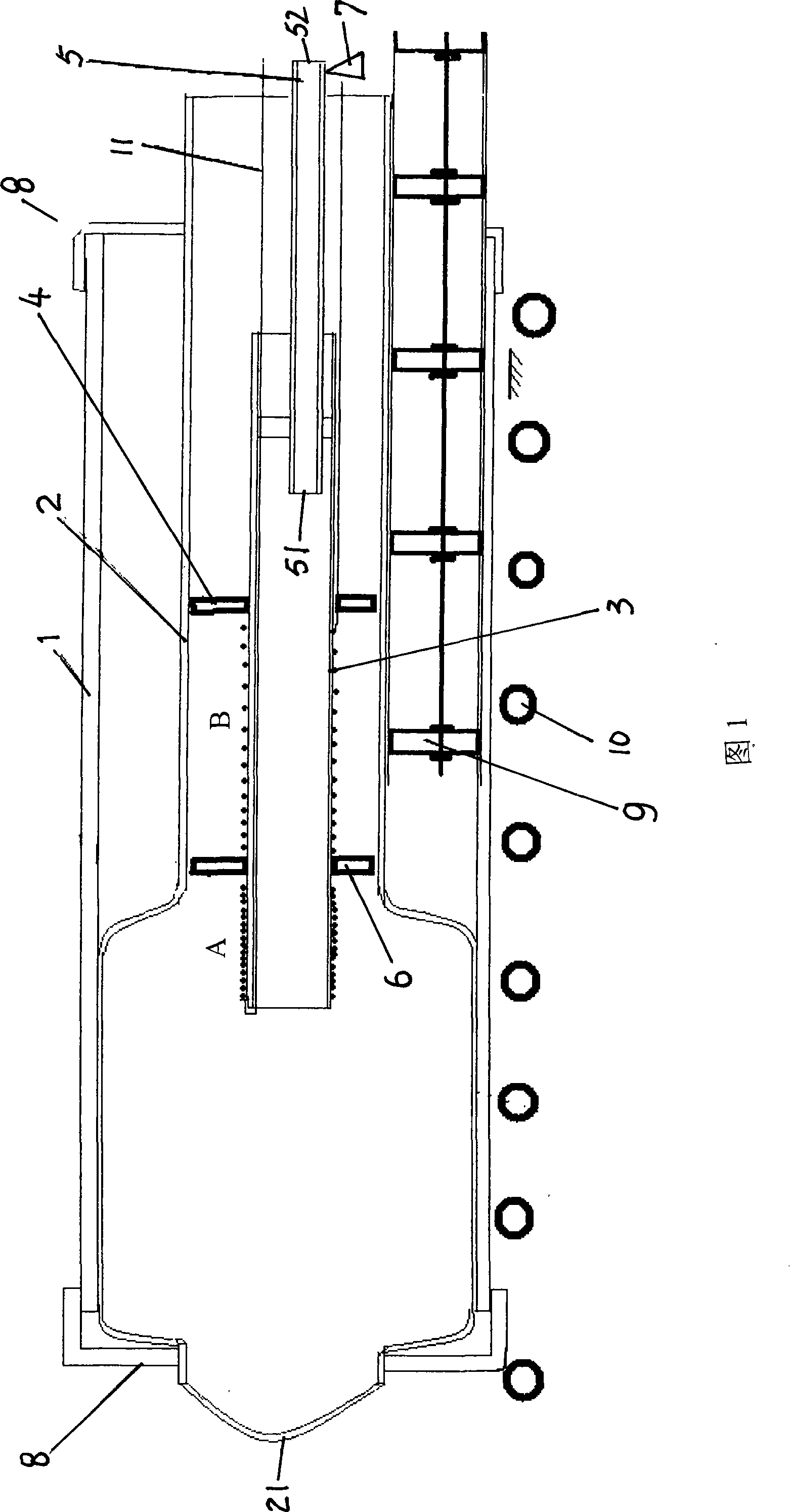
[0017] Please refer to shown in Fig. 1, the working principle schematic diagram of the embodiment of the present invention, the method of the present invention comprises the following steps in sequence:

[0018] (1), drawing the glass tube 2 corresponding to the length of the steel tube 1;

[0019] (2), put the glass tube 2 into the steel pipe 1, the glass tube support 9 is arranged at the lower part of the glass tube 2 in the steel pipe 1, and the steel pipe 1 is positioned on the moving guide roller 10;

[0020] (3), one end 21 of glass tube 2 is closed, glass tube snap rings 8 are respectively sleeved outside the two ends of glass tube 2, and the outer rings of two glass tube snap rings 8 are placed outside the steel pipe 1 at the same end, and then the high-frequency The induction heating body 3 is placed in the glass tube 2 and is located at the center of the glass tube 2. In this embodiment, the lower part of the high-frequency induction heating body 3 in the glass tube ...


PUM

PropertyMeasurementUnit
hardnessaaaaaaaaaa
hardnessaaaaaaaaaa
hardnessaaaaaaaaaa

Abstract

The invention discloses a method for arranging glass lining in a steel pipe. The method comprises the steps as follows: a glass pipe is arranged in the steel pipe, and a high frequency induction heater is arranged in the glass pipe. The high frequency induction heater firstly heats the glass pipe heat radiation above 650 DEG C and the steel pipe heats through the glass pipe radian heat and the high frequency induction heater to ensure that the temperature in the surface of the steel pipe reaches 680 to 700 DEG C and the temperature outside the surface of the steel pipe is below 300DEG C. Simultaneously, the steel pipe moves forwards corresponding to the high frequency induction heater with relative moving speed of 300 to 400mm / min and then the compressed air with the pressure of 0.1 to 0.3 MPa passes through the breather pipe to attach the emollient glass pipe at the wall of the steel pipe. The method can control the heating layer of the inner surface of the steel pipe to be very thin, ensure the steel pipe under the smallest heat impact, maintain the strength of the steel pipe under the supply state, improve the processing speed and reduce the production cost.

Description

technical field [0001] The invention relates to a method for lining a steel pipe with glass. Background technique [0002] Petroleum pipelines can be divided into surface oil pipelines and downhole oil production pipelines. Corrosion, wax deposition and eccentric wear (wear) are the most common things in the actual use of petroleum pipelines. Currently, commonly used anti-corrosion technologies include Ni-P plating technology, Nitriding technology, titanium nano-polymer paint coating technology, FRP pipeline anti-corrosion technology, and the introduction of the American Saike-54 coating technology, etc., all have some disadvantages after being applied to oil pipelines, and no single process can meet the requirements at the same time. Anti-corrosion, anti-waxing and anti-eccentric wear performance requirements, and each has fatal defects, such as the environmental pollution problem of Ni-P plating and the problem of coating voids, the embrittlement of pipe thread caused by n...

Claims


Application Information

Patent Timeline
Patent Type & Authority Patents(China)
IPC IPC(8): C03C27/02F16L57/06F16L58/14
Inventor 刘喜明马风雷高原
Owner CHANGCHUN UNIV OF TECH
Learn More