Etch stop layer and its forming method

A technology of etching barrier layer and manufacturing method, which is applied in the direction of electrical components, electrical solid devices, semiconductor/solid device manufacturing, etc., and can solve problems affecting packaging process, device reliability, interlayer dielectric layer and interlayer dielectric Layer interface adhesion and other issues

Active Publication Date: 2008-06-04
SEMICON MFG INT (SHANGHAI) CORP +1
View PDF1 Cites 19 Cited by
  • Summary
  • Abstract
  • Description
  • Claims
  • Application Information

AI Technical Summary

Problems solved by technology

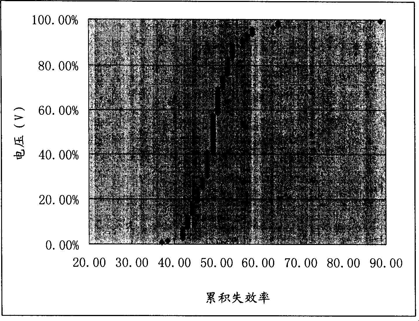
[0005] The problem solved by the present invention is that the structure of the etch barrier layer of the low dielectric constant dielectric layer in the prior art is not dense enough, resulting in too low breakdown voltage of the interlayer dielectric layer, causing device reliability problems, and at the same time du...

Method used


Image

  • Etch stop layer and its forming method
  • Etch stop layer and its forming method
  • Etch stop layer and its forming method

Examples


preparation example Construction

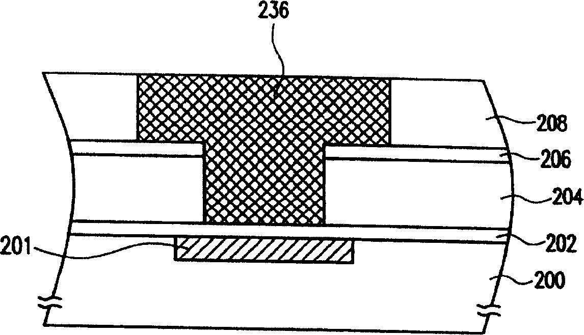
[0039] Figure 4A to Figure 4D It is a schematic diagram of the second embodiment of forming an etching stopper layer on a semiconductor substrate by using the preparation method of the present invention. The specific embodiment of the present invention will be described in detail below in conjunction with the accompanying drawings.

[0040] Such as Figure 4A As shown, a semiconductor substrate 31 with a conductive layer 32 is provided, and the semiconductor substrate 31 has semiconductor devices and wiring layers. To simplify the illustration, only a flat substrate with a conductive layer is shown here. Form the first etch barrier layer 41 on the semiconductor substrate 31 and the conductive layer 32, the first etch barrier layer 41 is silicon nitride, the stress range of the silicon nitride is -1600 to -2000MPa, the nitride The stress of silicon is compressive stress.

[0041] Next, if Figure 4B As shown, a first etch stop layer 41 is formed on a semiconductor substrat...


PUM

PropertyMeasurementUnit
Stressaaaaaaaaaa

Abstract

The invention relates to a method for forming an etch stop layer, which comprises an etch stop layer formed on a substrate; the etch stop layer is silicon nitride, the stress range of which is from -1, 600 to -2, 000MPa and the stress of which is compressive stress. The invention further provides a structure of a semiconductor device and a manufacturing method thereof. The invention adopts the silicon nitride with a high stress as the etch stop layer. As the silicon nitride has a relative high compactness, and at the same time, the compressive stress of the silicon nitride with a high stress can neutralize a tensile stress of a dielectric layer with a low specific inductive capacity, interface characteristics between the dielectric layer and the dielectric layer, Cu and the dielectric layer are changed, thus realizing the object of increasing the breakdown voltage between layers of the dielectric layer and the reliability of the device.

Description

technical field [0001] The invention relates to the field of semiconductors, in particular to an etching barrier layer and a forming method thereof. Background technique [0002] With the development of IC technology, the size of devices is getting smaller and smaller, and the influence of interconnect RC delay on device turn-on speed is increasing, far exceeding the impact of gate delay, so reducing RC interconnect delay has become the focus of attention. On the one hand, people introduce the use of Cu with low resistivity instead of Al with high resistivity to reduce the interconnection resistance, and apply it to the process of 0.25μm and below; on the other hand, people introduce low dielectric constant materials to reduce the number of metal interconnections. capacitance between. In order to solve the problem of Cu diffusion contamination, a thin layer of Cu barrier layer-Ti / TiN or Ta / TaN is deposited before depositing Cu; in order to solve the problem of difficult etc...

Claims


Application Information

Patent Timeline
IPC IPC(8): H01L21/318H01L21/768H01L23/532
Inventor 陈玉文邹晓东陈昱升
Owner SEMICON MFG INT (SHANGHAI) CORP
Why Eureka
Try Eureka