Circuit board structure and its manufacture method

A manufacturing method and technology of circuit boards, which are applied in the fields of printed circuit manufacturing, circuits, printed circuits, etc., can solve problems such as the decrease in the excellent rate of circuit board manufacturing, the difficulty in effectively reducing the thickness of multi-layer circuit boards, and the increase in the thickness of circuit boards, so as to avoid The wiring density on the surface of the circuit board, the effect of avoiding the increase in the thickness of the packaged product, and the reduction in the size of the packaged product

Inactive Publication Date: 2008-06-04
PHOENIX PRECISION TECH CORP
View PDF0 Cites 24 Cited by
  • Summary
  • Abstract
  • Description
  • Claims
  • Application Information

AI Technical Summary

Problems solved by technology

[0007] However, in the above-mentioned method for manufacturing a multi-layer circuit board, the insulating layer structure with a thin metal layer on the surface is used as the core layer (core), and the circuit is manufactured on the core layer to form a core circuit board, and then Layer-up manufacturing can also be performed on the core circuit board to form a multilayer circuit board with the required electrical design, thus making it difficult to effectively reduce the thickness of the final multilayer circuit board, which is not conducive to the development of miniaturized semiconductor packaging structures trend
If the thickness of the core layer is reduced to ultra-thin, for example, below 60 μm, the productivity of multilayer circuit boards will face severe challenges, and the manufacturing yield of circuit boards will be greatly reduced
[0008] In addition, the core circuit board has more plug holes and brushing manufacturing processes in the manufacturing method, which will increase the manufacturing cost of the circuit board
It is especially important that many plated through holes (PTH) are formed in the core c

Method used


Image

  • Circuit board structure and its manufacture method
  • Circuit board structure and its manufacture method
  • Circuit board structure and its manufacture method

Examples


Embodiment Construction

[0061] Embodiments of the present invention are described below through specific specific examples, and those skilled in the art can easily understand other advantages and technical effects of the present invention from the content disclosed in this specification. The present invention can also be implemented or applied through other different specific embodiments, and various modifications and changes can be made to the details in this specification based on different viewpoints and applications without departing from the spirit of the present invention.

[0062] see Figure 2A to Figure 2H A schematic cross-sectional view of the first embodiment of the manufacturing method of the circuit board structure of the present invention is described in detail.

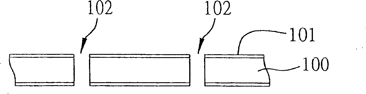
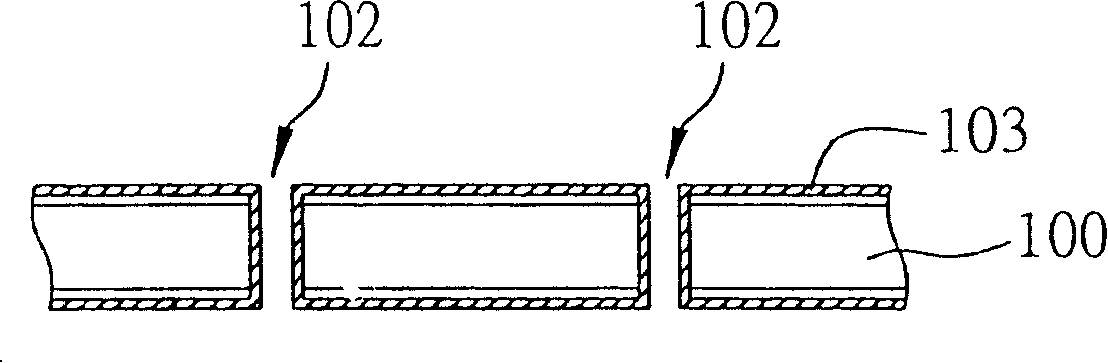
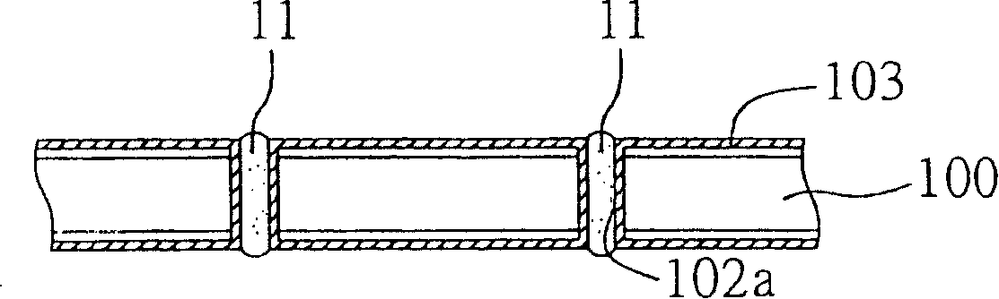
[0063] Such as Figure 2A As shown, a carrier 20 is first provided, which is an insulating plate 202 with a metal layer 201 on the surface, wherein the insulating plate 202 can be made of organic materials, and the metal lay...


PUM


Abstract

The invention relates to a circuit board structure and a manufacturing method thereof, which comprises the following steps: a bearing device is provided as an insulation plate which has a metal layer on a surface; an insulation protection layer is formed on the bearing device and a plurality of openings are formed in the insulation protection layer for discovering the metal layer; a circuit structure is formed in the surface of the insulation protection layer and in the openings to electrical connect the circuit structure with the metal layer; a dielectric layer is formed on the insulation protection layer and on the circuit structure and a plurality of openings are formed on the dielectric layer, thus exposing part of the circuit structure. The bearing device can be removed then for forming a circuit plate without a chip layer, thus reducing the circuit plate thickness and being conducive to decreasing the size of the sealed products and enhancing the performance so as to go in line with the development trend of miniaturization of electrical products.

Description

technical field [0001] The invention relates to a circuit board structure and a manufacturing method thereof, in particular to a circuit board structure without a core layer (core) and a manufacturing method thereof. Background technique [0002] With the development of semiconductor packaging technology, different packaging forms have been developed for semiconductor devices. Traditional semiconductor devices mainly install a semiconductor component such as an integrated circuit on a package substrate or a lead frame, and then The semiconductor component is electrically connected to the packaging substrate or the lead frame, and then packaged with glue. Among them, Ball grid array (BGA), such as PBGA, EBGA, FCBGA, etc., is an advanced semiconductor packaging technology, which is characterized in that a packaging substrate is used to place semiconductor components, and automatic alignment (Self- Alignment) technology to implant a plurality of solder balls arranged in a grid...

Claims


Application Information

Patent Timeline
IPC IPC(8): H01L21/48H01L23/498H05K1/02H05K3/00
CPCH01L2924/0002
Inventor 王杏如王仙寿许诗滨
Owner PHOENIX PRECISION TECH CORP
Why Eureka
Try Eureka