
Heat radiation method for high-power electronic part and heat radiation device using this method

A technology for electronic devices and heat dissipation methods, applied in the direction of cooling/ventilation/heating transformation, etc., can solve the problems of many consumables for heat dissipation plates, increase wind resistance, and high processing costs, and achieve the effects of high heat exchange efficiency, temperature control, and small size.

Inactive Publication Date: 2008-06-04
沈国忠
View PDF0 Cites 26 Cited by
  • Summary
  • Abstract
  • Description
  • Claims
  • Application Information

AI Technical Summary

Problems solved by technology

[0004] Forced air cooling is to install the heat-generating electronic components on a heat sink, and blow the relatively cold air from the surrounding environment to the heat sink of the heat sink through the fan to take away the heat. The disadvantage of this cooling method is: for high-power devices , due to the large amount of heat generated, a bulky radiator made of high thermal conductivity material is required to take away the heat, so the result is that the volume, weight, and cost of the cooling system are greatly increased; multiple large-flow fans are required Forced blowing of the radiator, since the flow rate of the fan is directly proportional to the size and cost, the size and cost of the electronic equipment are greatly increased; the electronic equipment using forced air cooling has very high requirements on the ambient temperature, humidity and cleanliness High, these high-power electronic devices generally can only work indoors, and need to install high-power air conditioners for refrigeration and dehumidification. , which increases the wind resistance and reduces the efficiency of the fan; the fan produces a lot of noise when it is working, which has a great adverse effect on the surrounding environment; therefore, forced air cooling is only suitable for small-power electronic equipment, or working Medium and low power electronics in benign environments
This heat sink has the disadvantages of many consumables and high processing costs

Method used


Image

  • Heat radiation method for high-power electronic part and heat radiation device using this method
  • Heat radiation method for high-power electronic part and heat radiation device using this method
  • Heat radiation method for high-power electronic part and heat radiation device using this method

Examples


Embodiment Construction

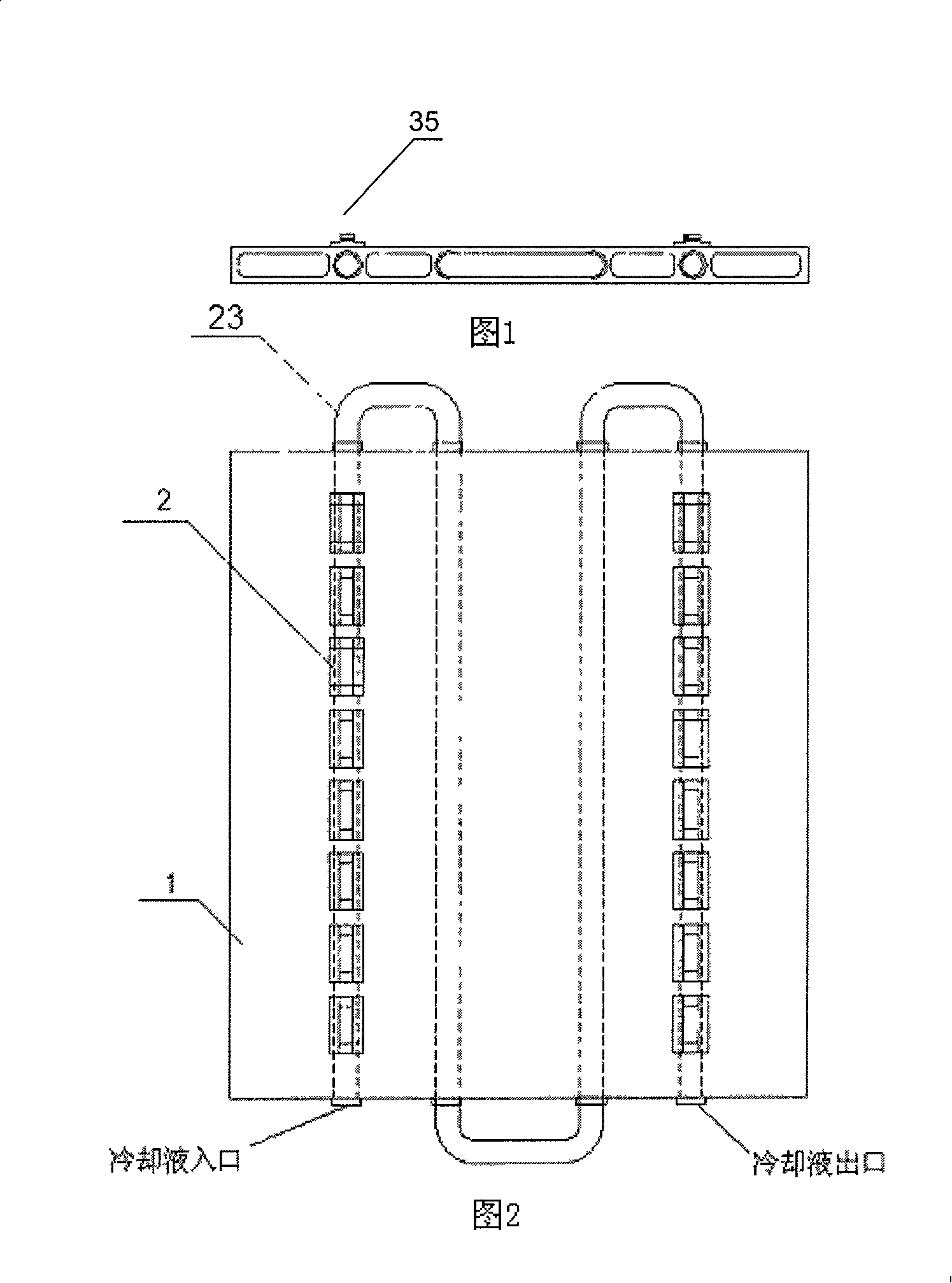
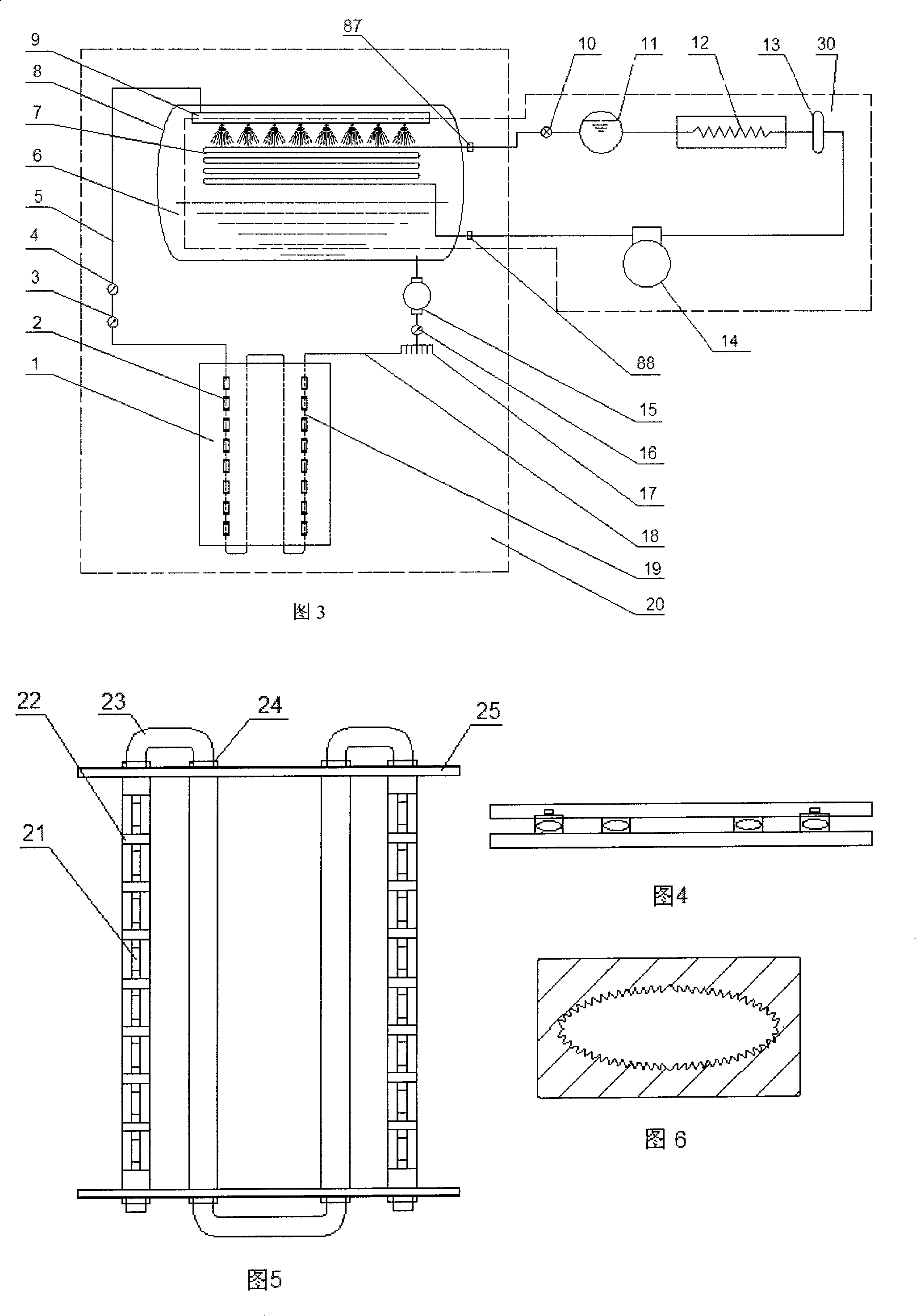
[0040]A method for heat dissipation of high-power electronic devices provided by the present invention, the method adopts a two-stage circulating cooling device, wherein: the first-stage circulating cooling device is a circulating liquid cooling device, and the circulating liquid in the circulating liquid cooling device is equipped with The radiator of the heating electronic component performs heat exchange to cool the heating element on the radiator; the second-stage circulating cooling device is a heat pump refrigeration device, and the heat pump refrigeration device cools the circulating fluid. The liquid-solid phase point of the cooling liquid in the circulating liquid cooling device is not lower than minus 20°C, and the boiling point is not lower than 90°C. In this way, the working temperature range of the cooling liquid can be controlled, and the component failure caused by the temperature being too low or too high can be avoided. Specifically, use 30% to 60% ethylene gl...


PUM

PropertyMeasurementUnit
Boiling pointaaaaaaaaaa

Abstract

The invention relates to a technology for heat dissipation, in particular, a method of heat dissipation and a device of heat dissipation for a large power electronic device. The invention adopts a two-level cyclic cooling device, among which, a first level cooling device is a cyclic liquid cooling device, and the cyclic liquid of the cyclic liquid cooling device exchanges heat with a radiator fixed with a heating electronic device so as to cool the heating device on the radiator; while a second cyclic cooling device is a heat pump refrigerating plant which cools the cyclic liquid. The invention cools the large power electronic device by combining liquid cooling and evaporative cooling. The invention has the advantages of small volume, manageable temperature, low noise, low cost, and high efficiency of heat exchange, etc.

Description

technical field [0001] The invention relates to a heat dissipation technology and a heat dissipation device of an electronic device, in particular to a heat dissipation method for a high-power electronic device used for a large power dissipation electronic device and a heat dissipation device using the method. Background technique: [0002] Power electronic components are mainly used in power conversion, rectification equipment, electric drive equipment, radio / television transmission, forwarding equipment, and power amplification, power absorption, and high-power power supply in high-power communication equipment. In the working state of high current and high power, the power dissipation of these electronic devices is usually very large, especially for power amplifier tubes in digital radio / television transmission, transponder equipment and high-power digital communication equipment. In order to reduce the cost and reduce the size, the direction of increasing the output powe...

Claims


Application Information

Patent Timeline
IPC IPC(8): H05K7/20
Inventor 沈国忠
Owner 沈国忠
Learn More