Electrothermal actuator and technique of producing the same

A technology of micro-actuator and preparation process, applied in piezoelectric devices/electrostrictive devices, piezoelectric/electrostrictive/magnetostrictive devices, manufacturing tools, etc., can solve problems such as cell manipulation limitations, killing cells, etc. , to achieve the effect of not easy to break, reduce heat dissipation, and large displacement output

Inactive Publication Date: 2008-06-11
SHENYANG INST OF AUTOMATION - CHINESE ACAD OF SCI
View PDF0 Cites 5 Cited by
  • Summary
  • Abstract
  • Description
  • Claims
  • Application Information

AI Technical Summary

Problems solved by technology

[0003] In the application of MEMS microactuators for cell manipulation in the prior art, it is limited due to constraints such as displacement, force output, and working environment, that is, water will be electrolyzed when the potential on the holder reaches above 2V, so It is not suitable for use in liquid environments; currently, micro-magnetic actuators still require an independent mag...

Method used


Image

  • Electrothermal actuator and technique of producing the same
  • Electrothermal actuator and technique of producing the same
  • Electrothermal actuator and technique of producing the same

Examples


Embodiment 1

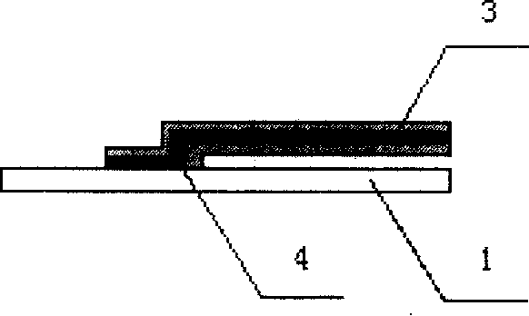
[0035] Such as figure 1 As shown, the electrothermally driven microactuator of the present invention has the effect of electrothermal braking, and can be designed and processed to have multiple cantilever beam structures (fingers) to complete microoperations such as cell capture and clamping. Each cantilever beam is installed on a silicon substrate and has a three-layer structure. Titanium and platinum are used as resistance heating materials, and titanium and platinum are placed between parylene C (a polymer material); that is, titanium and platinum are clamped by parylene C. The three-story structure constitutes a cantilever beam. This embodiment is 4 cantilevers (or fingers), see Figure 4 .

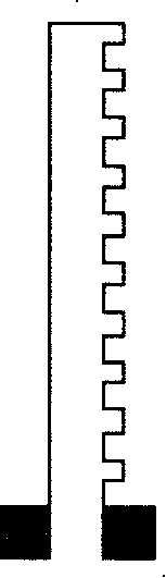
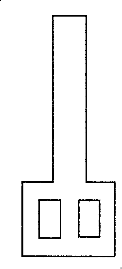
[0036] Among them: the resistance heating material can be a few-shaped structure or any shape (see figure 2 , 3 ).

[0037] The maximum working temperature of the thermally driven micro-actuator cantilever beam of the present invention is 70°C, and the voltage when it is fully b...

Embodiment 2

[0051] This embodiment is 2 cantilevers (or fingers, see Figure 8 ). Its processing technology differs from embodiment 1 in that:

[0052] used on silicon chips Silicon oxide is grown under the same light conditions as the substrate 1; the thickness of photoresist is 1.0 μm on the desired part of the silicon substrate; the thickness of parylene C as the first layer 3 is 0.35 μm; the thickness of the electrothermal material titanium is 0.055 μm , the platinum thickness is 0.195 μm. The thickness of parylene C as the third layer 3 is 0.24 μm;

Embodiment 3

[0054] The present embodiment is 6 cantilever beams, and its processing technology differs from embodiment 1 in that:

[0055] used on silicon chips Silicon oxide is grown under the same light conditions as the substrate 1; the thickness of photoresist is 1.8 μm on the desired part of the silicon substrate; the thickness of parylene C as the first layer 3 is 0.35 μm; the thickness of the electrothermal material titanium is 0.045 μm , the titanium thickness is 0.205 μm. The thickness of parylene C as the third layer 3 is 0.26 μm;

[0056] The two usage states of the six-finger gripper in this embodiment are as follows: Figure 7-1 , 7-2 shown. The index of the present invention should be determined according to the actual application.


PUM

PropertyMeasurementUnit
Thicknessaaaaaaaaaa
Thicknessaaaaaaaaaa
Thicknessaaaaaaaaaa

Abstract

The invention relates to an applied technology of micro-robots in the fields of cell operation and cell separation, in particular to a micro-actuator driven by heating from electricity and a process for preparation. The micro-actuator driven by heating from electricity is composed of a polymeric material of Parylene C and electron-heating materials of titanium and platinum and is capable of realizing the operation of clamping cells under the fluid environment. The actuator is a multiple cantilever beam structure and is fixed on a silicon substrate, and each cantilever beam is a three-layer structure of parylene C clamping the electron-heating materials. The processing technique employs screen-printing technology of MEMS (micro-electro-mechanism system). The invention is capable of being electrically driven, and parylene C is taken as heat/ electricity/ fluid isolation material, then a heater formed by electron-heating materials is not exposed in the fluid, thereby having good biological adaptability and fluid environment adaptability, being capable of realizing cell operation and cell separation by controlling the temperature and providing automatic operation and application of localization detection, injection and measuring of cells.

Description

technical field [0001] The invention relates to the application technology of micro-robot technology in cell operation and separation, specifically an electrothermally driven micro-actuator composed of Parylene C polymer material and electrothermal material titanium and / or platinum and its preparation process. The cell clamping operation can be realized by generating electric heating at a low voltage in a liquid environment. Background technique [0002] The potential application of microrobotics in cell manipulation and isolation has attracted increasing attention. Biologists often use pipettes to separate cells before injecting DNA or nutrients into them. However, this method is limited by the size of the cells, e.g. if the cells are too small compared to the inner diameter of the pipette, a clump of cells can be inadvertently sucked into the pipette. Also, the pipette cannot be used to spin the cells, which is necessary during cell injection. [0003] In the applicatio...

Claims


Application Information

Patent Timeline
IPC IPC(8): B81B3/00B81C1/00B25J7/00
Inventor 李文荣陈浩然
Owner SHENYANG INST OF AUTOMATION - CHINESE ACAD OF SCI
Why Eureka
Try Eureka