
Method for manufacturing an SOI substrate

A manufacturing method and substrate technology, applied in semiconductor/solid-state device manufacturing, electrical components, circuits, etc., can solve problems such as peeling or cracks, low melting point, and difficulties in joint surfaces, and achieve the effect of suppressing surface roughness and reducing manufacturing costs

Inactive Publication Date: 2008-06-25
SHIN ETSU CHEM CO LTD
View PDF0 Cites 16 Cited by
  • Summary
  • Abstract
  • Description
  • Claims
  • Application Information

AI Technical Summary

Problems solved by technology

[0007] In other words, in the case of laminating a silicon substrate and a quartz substrate to produce an SOI substrate, there is a problem in that, in order to avoid peeling of the bonded surface due to thermal strain caused by the difference in thermal expansion coefficient between the two substrates, or cracks, etc., requiring low-temperature process; and heat treatment at a relatively high temperature in order to make the entire bonding surface in a good state, these two contradictory problems
However, the SOITEC method cannot solve this problem
In addition, when an inexpensive glass substrate or an organic thin substrate is used as an insulating substrate, since its melting point is low, a low-temperature process is required, and it is difficult to cope with this purpose with a known method that requires a high-temperature process.

Method used


Image

  • Method for manufacturing an SOI substrate
  • Method for manufacturing an SOI substrate

Examples


Embodiment 1

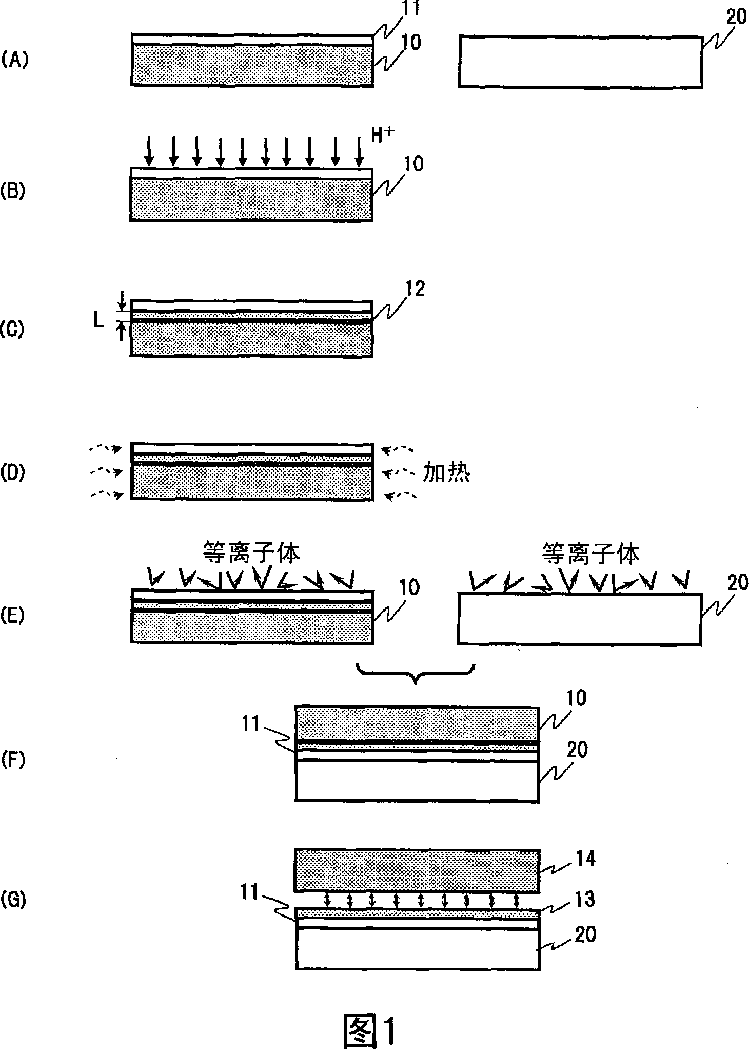
[0034] FIG. 1 is a diagram for explaining a process example of a method for manufacturing an SOI substrate of the present invention. In addition, in this embodiment, an oxide film is provided in advance on the surface of the silicon substrate, but this oxide film is not an essential configuration, and a general silicon substrate without an oxide film may be used.

[0035] The silicon substrate 10 shown in FIG. 1(A) is generally a single crystal silicon substrate; the supporting substrate is a quartz substrate 20 . Here, the single crystal silicon substrate 10 is, for example, a commercially available silicon substrate grown by the CZ method (Czochralski method), and its conductivity type, electrical characteristics such as resistivity, crystal orientation, crystal diameter, etc., It can be appropriately selected depending on the design value of the device, the process, or the representative area of ​​the device to be manufactured (for the SOI substrate to be manufactured by th...

Embodiment 2

[0053] In this embodiment, the thickness of the oxide film formed on the main surface of the silicon substrate 10 is studied and discussed.

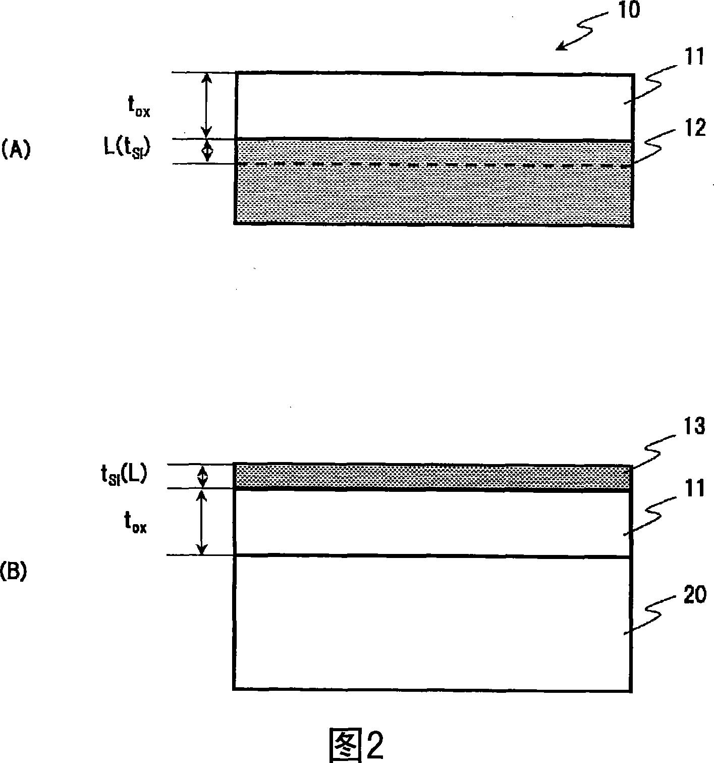
[0054] 2 is a cross-sectional view ( FIG. 2(A) ) for explaining a schematic shape of a bonding surface of a single-crystal silicon substrate used in the method for producing an SOI substrate of the present invention; and a silicon film having a silicon film obtained by peeling A schematic cross-sectional view of the SOI substrate (FIG. 2(B)).

[0055] As shown in FIG. 2(A) , a film thickness t is provided on one of the principal surfaces (bonding surfaces) of the single crystal silicon substrate 10 ox The silicon oxide film 11 is formed near the substrate surface, and the hydrogen ion implantation layer 12 is formed at the average ion implantation depth L. In this embodiment, in order to suppress the occurrence of transfer defects and slip dislocations in the peeling process of the silicon thin film after bonding with the quartz substra...


PUM

PropertyMeasurementUnit
thicknessaaaaaaaaaa

Abstract

A method for manufacturing an SOI substrate, comprising: an ion implantation process, which is to form a hydrogen ion implantation layer on the main surface side of a silicon substrate; a surface treatment process, which is to at least one of the insulating substrate and the above-mentioned silicon substrate activation treatment on the main surface of the above-mentioned insulating substrate; a bonding process, which is to bond the main surface of the above-mentioned insulating substrate and the main surface of the above-mentioned silicon substrate; The silicon thin film is mechanically peeled off to form a silicon film on the main surface of the insulating substrate, and the temperature of the silicon substrate in the ion implantation process is maintained at 400° C. or lower. The method of the invention can suppress the surface roughness of the stripped SOI film, and ensure that the entire surface of the SOI substrate has a uniform thickness of the SOI film. Since all are low-temperature processes, the occurrence of transfer defects or slip dislocations can be suppressed, and high-quality SOI wafers can be obtained.

Description

technical field [0001] The present invention relates to a method of manufacturing an SOI substrate having a silicon film on an insulating substrate. Background technique [0002] An SOI (Silicon on Insulator) wafer has been valued as a semiconductor substrate capable of improving the performance of a semiconductor device. This is because by adopting the SOI structure and embedding the oxide film under the single crystal silicon thin film, the parasitic capacitance can be reduced, the operation speed can be improved, and the power consumption can be suppressed. However, until now, SOI wafers have not become the mainstream of substrates for manufacturing LSI devices. The reason for this is that the manufacturing cost of an SOI wafer is about several times (or more than several times) that of a normal SOI wafer. [0003] Also, the SOQ (Silicon on Quartz) wafer having a silicon thin film on a quartz substrate is expected to be applied to an optical device (device), such as an ...

Claims


Application Information

Patent Timeline
Patent Type & Authority Applications(China)
IPC IPC(8): H01L21/00H01L21/02H01L21/20H01L21/265H01L21/336H01L21/762H01L21/84
CPCH01L21/76254
Inventor 秋山昌次久保田芳宏伊藤厚雄田中好一川合信飞坂优二
Owner SHIN ETSU CHEM CO LTD
Learn More