Coating blade for processing cast iron

A technology of coating inserts and coatings, applied in the direction of layered products, etc., can solve the problems of the overall performance limitation of the tool and the lack of gradient structure, achieve green and environmentally friendly dry cutting, avoid the decline of strength and toughness, and improve the cutting edge. the effect of strength

Active Publication Date: 2008-07-09
ZHUZHOU CEMENTED CARBIDE CUTTING TOOLS CO LTD
View PDF15 Cites 17 Cited by
  • Summary
  • Abstract
  • Description
  • Claims
  • Application Information

AI Technical Summary

Problems solved by technology

The tool matrix improves the high temperature resistance of the tool by adding a small amount of carbide cubic phase, but the overall performance of the tool is limited because it does not have a gradient structure

Method used


Image

  • Coating blade for processing cast iron

Examples


Embodiment 1

[0032] A coated insert according to the invention, comprising a hard phase based on tungsten carbide (WC) and a binding phase based on cobalt (Co), by adding a small amount of nitrogen-containing cubic compounds or consisting of these cubic compounds Solid solution, and the powder mixture is pressed, and the cemented carbide tool is sintered by gradient sintering technology (sintered at 1440°C, cooled under a de-N atmosphere after high temperature sintering), and a layer of bonding phase is formed on the surface of the cemented carbide substrate enriched surface zone, forming a layer of cubic phase enriched zone under the binder phase enriched surface zone. The thickness L2 of the bonding phase-enriched surface region b is 50 μm, and the content of Co in the bonding phase-enriched surface region is 1.2 times the nominal content of Co in the cemented carbide matrix; by using chamfering, Rounding and other treatments remove the bonded phase-enriched surface area on the surface o...

Embodiment 2

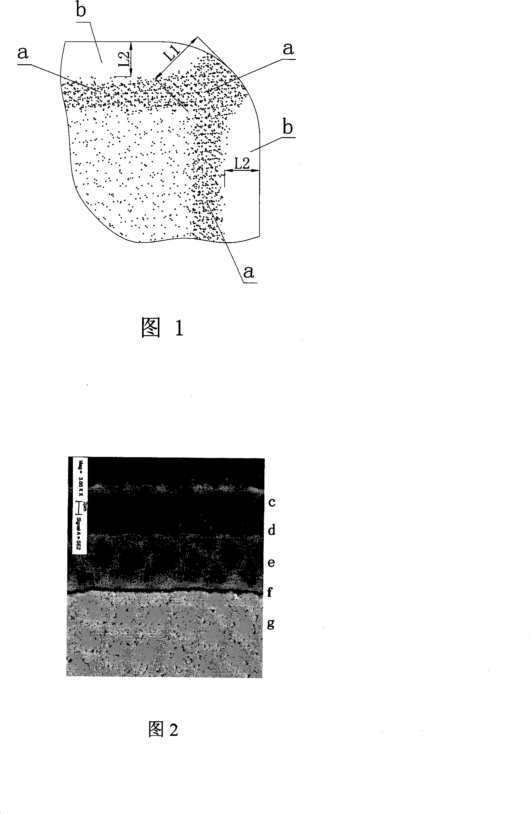
[0040] The preparation method of the matrix in this example is the same as in Example 1, and the components and content of the prepared blade matrix are the same as those in Example 1, but by controlling the gradient sintering process, a 20 μm thick binder phase enriched surface area is formed on the surface of the matrix , the content of Co in the bonding phase-rich surface area is 1.3 times the nominal content of Co in the cemented carbide matrix; through chamfering and rounding, a bonding phase rich in L2 = 20 μm thick is formed on both sides of the cutting edge The surface area b is concentrated, and the middle fan-shaped part exposes the cubic phase enrichment area a with good high temperature performance (as shown in Figure 1). The thickness L1 of the cubic phase enrichment area is 40 μm, and the content of the cubic phase compound is the cubic phase in the matrix 1.45 times the nominal content of the compound.

[0041] The substrate g is coated according to the process ...

Embodiment 3

[0043] The preparation method of the substrate in this example is the same as that in Example 1, and the composition of the prepared cemented carbide matrix includes: 5.5wt% Co, 3.5wt% Ti and Ta cubic carbonitride, and the balance is WC. On both sides of the cutting edge, there is a bonded phase enriched surface area b with a thickness of L2 = 35 μm, and the content of Co in the bonded phase enriched surface area b is 1.4 times the nominal content of Co in the cemented carbide matrix; and the middle fan-shaped part It is a cubic phase-enriched region a with good high-temperature performance. The thickness L1 of the cubic-phase-enriched region a is 70 μm, and the content of the cubic phase compound is 1.15 times the nominal content of the cubic phase compound in the matrix.

[0044] In this embodiment, the substrate is coated by the process method of Example 1 to obtain the same coating structure as that of Example 2.


PUM

PropertyMeasurementUnit
thicknessaaaaaaaaaa
crystal sizeaaaaaaaaaa
thicknessaaaaaaaaaa

Abstract

The invention discloses a coated tip used to processing cast iron, which comprises a hard alloy basal body and a coating. The invention is characterized in that the hard alloy basal body comprises 2 percent to 12 percent of cobalt by weight and 0.2 percent to 3.5 percent of cubic-structure compound of metallic elements from the families of IVb, Vb and/or VIb in the periodic table by weight. A binding phase surface enrichment area is formed on both sides of the cutting edge of the basal body. The middle pie-slice section of the binding phase surface enrichment area is a cubic structure enrichment area. The coating comprises an innermost layer of equiaxed grain TiCxNyOz, a middle layer of columnar crystal TiCxNy 2 microns to 13 microns thick, a transition layer of TiCxNyOz and an outer layer of fine crystal Alpha-Al2O3 4 microns to 12 microns thick. The tip disclosed by the invention not only has the characteristics of high wearing feature, high strength and high versatility, but also integrates the toughness and the plastic deformation resistance well. Accordingly, the invention is in particular applicable for processing cast iron.

Description

technical field [0001] The invention relates to a coated blade, in particular to a coated blade for processing cast iron. Background technique [0002] Currently, during the machining of carbide-coated tools, there are two failure regimes: wear and breakage. Tool wear mainly includes abrasive wear, adhesive wear, diffusion wear and oxidation wear. Under different cutting conditions, when processing workpieces of different materials, the main reason for the wear may be one or two of them. Diffusion wear and oxidation wear are the main types. Tool damage is mainly plastic deformation damage and brittle damage (chipping, chipping, peeling, crack damage). Cemented carbide tools have high hardness and high brittleness. They are powder sintered bodies. The structure may be uneven and have defects. When it has the nature of intermittent cutting, it is prone to brittle fracture by mechanical and thermal shock. The test shows that the early damage of the tool is less affected by...

Claims


Application Information

Patent Timeline
Patent Type & Authority Applications(China)
IPC IPC(8): B32B5/14B32B33/00B32B9/00C22C29/00
Inventor 陈响明刘王平周定良李屏王社权
Owner ZHUZHOU CEMENTED CARBIDE CUTTING TOOLS CO LTD
Why Eureka
Try Eureka